background image


E2S Warning Signals 

Impress House, Mansell Road, Acton, London W3 7QH    sales@e2s.com         e2s.com


       D221

-

00

-

001

-

IS

-

UL Issue A  26/04/2021


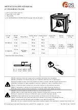
FIRE INSTRUCTION & SERVICE MANUAL


A112N Range AlertAlarm Sounder UL464 / CAN/ULC

-

S525 


Model: A112NDC


• 

-

40°C to +66°C / 

-

40°F to +151°F


• 

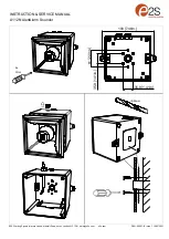
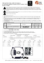
Units can be mounted using the 2

-

off ø9mm holes in the mounting lugs or through the back of the housing using the supplied gasket 

seal.


• 

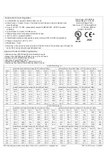
A112NDC024 is approved for use as an audible signal appliance for fire alarm use –


Public Mode (UL464 & CAN/ULC

-

S525) and pro-

duces a minimum sound pressure level of P1: US: 93.37dB(A); CA: 101.6dB(A) / P2: US: 94.64dB(A); CA: 103.9dB(A) at 10 feet, 

(figures @ worst case 11.5Vdc).


• 

A112NDC024 produces a minimum sound pressure level of P1: US: 95.6dB(A); CA: 104.3dB(A) / P2: US: 98.55dB(A); CA: 107.6dB(A) 

at 10 feet (@24Vdc) 


• 

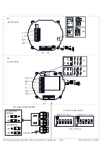
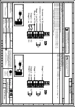
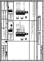
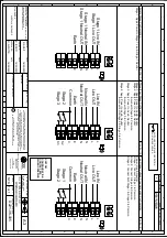
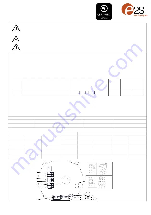
For Fire Alarm applications, the Sounder Volume must be at the highest setting, (see volume control section). For fire alarm use, Tone 

12 as shown below must be selected:


• 

Connection Terminals: Pluggable


AC: 1.0 

-

 2.5mm

2

 / AWG18 

-

 AWG12


                                  DC: 0.2 

-

 2.5mm

2

 / AWG24 

-

 AWG12


• 

Terminal Tightening torque 0.4Nm


• 

To maintain Ingress Protection, cable entries must be fitted with suitably rated cable glands or stopping plugs


• 

Units can be located indoor or outdoor wet use, wall or ceiling mounted and there are no limitations on orientation


• 

Factory finishes are not intended to be modified


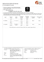
Surge Current Ratings for use in fire alarm systems


Model


Nominal Voltage


Voltage Range


Initial Peak


Initial RMS


A112NDC024


24V dc 


11.5 

-

 54V dc 


P1: 1455mA / P2: 1164mA


P1: 140mA / P2: 286mA


A112NDC024 Sounder Directional Characteristics for Canadian Fire CAN/ULC

-

S525 at 10 feet


Horizontal Axis


Vertical Axis


Angle


OSPL


Angle


OSPL


Angle


OSPL


Angle


OSPL


Ref. 90°


103.7 dB(A)


Ref. 90°


103.7 dB(A)


Ref. 90°


103.8 dB(A)


Ref. 90°


103.78dB(A)


129°


-

3 dB(A)


49°


-

3 dB(A)


126°


-

3 dB(A)


49°


-

3 dB(A)


131°


-

6 dB(A)


39°


-

6 dB(A)


140°


-

6 dB(A)


40°


-

6 dB(A)


180°


92.6 dB(A)


91.2 dB(A)


180°


92.5 dB(A)


90.8 dB(A)


Attention: Installation must be carried out by an electrician in compliance with the National Electrical Code, NFPA 70, and the National Fire Alarm 
Signaling Code, NFPA 72 or CSA 22.1 Canadian Electrical Code, Part I, Safety Standard for Electrical Installations, Section 32. /  L'installation doit 
exclusivement être réalisée par du personnel qualifié, conformément au code national d'électricité américain, NFPA 70, et le code national d

alarrme 

incendie et de signalisation NFPA 72 ou CSA 22.1 Code canadien de l'électricité, première partie, norme de sécurité relative aux installations électriques, 
Section 32


Attention: Disconnect from power source before installation or service to prevent electric shock / Débranchez

-

le de la source d'alimentation avant l'instal-

lation ou l'entretien pour éviter tout choc électrique.


Attention: Do not paint / Ne pas Peinturer


+


+


S2


S3


S2                                                                              S1


P1


P2


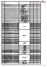
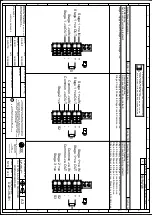
1000Hz(0.5s on, 0.5s off)x3 + 1s gap ISO 8201 Temporal 
Pattern

Stage 1
Set DIP
SW 1
Tone No.

Tone Description

Tone Visual

Stage 1 & 2
DIP SW 1/2

 Settings

1 2 3 4 5 6

Stage 3
Set DIP

SW 1

(S3)

Stage 4
Set DIP

SW 1

(S2 + S3)

12

1 1 0 1 0 0

1000Hz 0.5s

0.5s

0.5s

0.5s

0.5s

1s

1

8

Summary of Contents for A112N

Page 1: ...Attenzione L installazione deve essere eseguita da un elettricista in conformità con i codici e le normative più recenti Atención La instalación debe ser realizada por un electricista de acuerdo con los últimos códigos y regulaciones Atenção A instalação deve ser realizada por um eletricista de acordo com os códigos e regulamentos mais recentes Внимание установка должна выполняться электриком в со...

Page 2: ...s com e2s com D221 00 001 IS Issue 1 10 05 2021 S2 S3 S2 S1 DC P1 P2 L N E C S2 S3 S2 S1 AC P1 P2 Default S2 Tone 1 Default S1 Tone 44 ON 1 OFF 0 AC DC See D221 95 001 DC Only see D221 06 001 H2 H1 ve switching Default H2 H1 ve switching Link W1 See D221 06 005 See D221 06 001 ...

Page 3: ...VICE MANUAL A112N AlertAlarm Sounder E2S Warning Signals Impress House Mansell Road Acton London W3 7QH sales e2s com e2s com D221 00 001 IS Issue 1 10 05 2021 4x 1Nm 190 7 48in 35 9 1 41in 35 9 1 41in 61 2 40in ø20mm ...

Page 4: ... Output Min Voltage 11 5 Vdc LAFmax T dB A Angle Tone 44 Tone 8 Tone 2 Tone 21 Tone 31 Tone 5 Tone 44 Tone 8 Tone 2 Tone 21 Tone 31 Tone 5 15 103 3 103 7 103 1 103 3 103 2 91 5 101 101 5 100 9 101 100 3 89 4 45 103 4 104 8 104 2 101 6 96 3 99 4 101 5 102 7 101 8 99 6 94 3 97 4 75 109 1 110 4 109 7 109 6 108 3 103 2 107 1 108 2 107 4 107 7 105 9 101 4 105 109 9 110 2 109 6 109 7 108 6 103 107 7 108...

Page 5: ...rating Current P1 Max Operat ing RMS P2 Nominal Operating Current P2 Max Operating RMS A112NDC024 12V dc 11 5 54V ac 280mA 280mA 376mA 430mA 24V dc 225mA 430mA 48V dc 122mA 223mA 115V ac 100 240V ac 50 60Hz 100mA 101mA A112NAC230 173mA 181mA 230V ac 65mA 105mA Max Operating current for worst case input voltage Nominal current at nominal voltage and Tone 44 The units have been tested and approved t...

Page 6: ... 0 0 0 1 0 1 0 0 0 0 1 1 0 0 0 1 1 1 0 0 0 0 0 0 1 0 0 1 0 0 1 0 0 0 1 0 1 0 0 1 1 0 1 0 0 0 0 1 1 0 0 1 0 1 1 0 0 0 1 1 1 0 0 1 1 1 1 0 0 0 0 0 0 1 0 1 0 0 0 1 0 0 1 0 0 1 0 1 1 0 0 1 0 0 0 1 0 1 0 1 0 1 0 1 0 0 1 1 0 1 0 1 1 1 0 1 0 1 1 0 1 1 0 0 0 1 1 1 0 0 1 1 1 1 0 0 0 0 0 0 1 0 1 0 0 0 1 1 1 0 0 0 1 0 0 1 0 0 1 1 0 1 0 0 1 0 1 1 0 0 1 1 1 1 0 0 1 0 0 0 1 0 1 0 1 0 1 0 1 1 0 1 1 0 1 0 1 1 1 0...

Page 7: ...age Range Initial Peak Initial RMS A112NDC024 24V dc 11 5 54V dc P1 1455mA P2 1164mA P1 140mA P2 286mA A112NDC024 Sounder Directional Characteristics for Canadian Fire CAN ULC S525 at 10 feet Horizontal Axis Vertical Axis Angle OSPL Angle OSPL Angle OSPL Angle OSPL Ref 90 103 7 dB A Ref 90 103 7 dB A Ref 90 103 8 dB A Ref 90 103 78dB A 129 3 dB A 49 3 dB A 126 3 dB A 49 3 dB A 131 6 dB A 39 6 dB A...

Page 8: ...OTTS OF A112N A121 DC SOUNDER WIRING DIAGRAMS INTRODUCTION NTS 1 3 OPTIONAL LINE MONITORING RESISTOR CUSTOMER SUPPLIED 14V MAX SYSTEM 120Ω MIN 2W MIN OR 1KΩ MIN 0 5W MIN 28V MAX SYSTEM 470Ω MIN 2W MIN OR 2 4KΩ MIN 0 5W MIN RECOMMENDED MINIMUM VALUES R1 Stage 1 ve IN Stage 1 ve OUT Common ve IN Common ve OUT Stage 2 ve Stage 1 ve IN Stage 1 ve OUT Common ve IN Common ve OUT Stage 2 ve Stage 3 ve R1...

Page 9: ... FOR STAGE OPERATION CUSTOMER SUPPLIED Stage 2 ve Common ve IN Common ve OUT Stage 1 ve OUT Stage 3 ve Stage 1 ve IN H2 H1 Stage 1 ve Stage 1 ve Stage 2 ve Stage 2 ve OF 2 3 R1 S2 S3 R1 S2 R2 OPTIONAL LINE MONITORING RESISTOR CUSTOMER SUPPLIED 14V MAX SYSTEM 120Ω MIN 2W MIN OR 1KΩ MIN 0 5W MIN 28V MAX SYSTEM 470Ω MIN 2W MIN OR 2 4KΩ MIN 0 5W MIN RECOMMENDED MINIMUM VALUES R1 Set H1 H2 to ve switch...

Page 10: ... E 7 8 6 5 D C 1 3 4 2 A B D221 06 001 R S RAIT B ISARD R N POTTS A112N A121 DC SOUNDER WIRING DIAGRAMS NTS Stage 1 ve Stage 1 ve Stage 2 ve Stage 2 ve OF 3 3 R1 R1 S2 R2 Two Stage Configuration Config 4 Line Stage Monitoring Use suitable monitoring relays modules Not to be used for reverse polarity monitoring Stage 1 Apply Power to Stage 1 ve Stage 1 ve Stage 2 Apply Power to Stage 2 ve Stage 2 v...

Page 11: ... 3 4 2 A B D221 06 005 R S RAIT B ISARD R N POTTS OF A112N A121 AC WIRING DIAGRAMS NTS 1 SWITCHES FOR STAGE OPERATION CUSTOMER SUPPLIED 1 Earth Earth Stage 2 Stage 3 Common Live IN Live OUT Neutral IN Neutral OUT Earth Stage 1 Stage 2 Common N N L L E N N L L E C N N L L E C S2 S3 Live IN Live OUT Neutral IN Neutral OUT Stage 1 Live IN Stage 1 Live OUT Stage 1 Neutral IN Stage 1 Neutral OUT Single...

Page 12: ...Page left Intentionally blank ...

Reviews: