background image

_______________________________________________________________________________________________________________________________ 

European Safety Systems Ltd.

   Impress House, Mansell Road, Acton, London W3 7QH           sales@e-2-s.com              Tel: +44 (0)208 743 8880 

                                                                                                                                                             www.e-2-s.com             Fax: +44 (0)208 740 4200 
Document No. IS 2446-76-P      Issue 1          25/02/13                                Sheet 4 of 6 

        Mod No: ACN0012


13) 

Sounder Tone Selection 


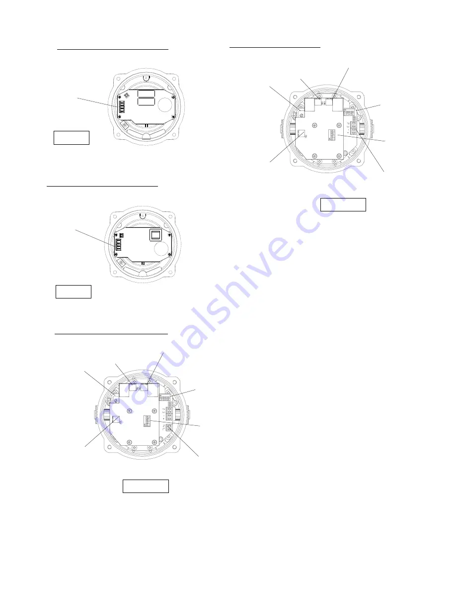
The  BExDCTS110-05D  combined  sounder  /  beacons  have 
32  different  tones  that  can  be  selected  by  the  DIP  switches 
on the sounder pcb (see figures 6 and 7). The tone table on 
page five shows the switch positions for the 32 tones.  


14) 

 Sounder Volume Control


T

he  BExDCTS110-05D  combined  sounder  /  beacon  has  a 

volume control to adjust the output level. To set the required 
output  level,  adjust  the  potentiometer  on  the  sounder  pcb 
(see  figure  6  &  7).  For  maximum  output  level  the 
potentiometer should be set to the fully clockwise position. 


15) 

Telephone  Setting  DIP  &  Continuous  or  Pulse 
Sounder Beacon Operation 

 
The  BExDCTS110-05D  combined  sounder  /  beacon  has  a 
number of modes of operation. The sounder and beacon can 
be set individually to either run continuously or pulsed at the 
cadence of the ringing tone. 
This is set by setting the DIP switches on the Telephone pcb 
(see figures 6 and 7).  
 
The Telephone Selection Table on page six shows the switch 
positions  1  -  4  for  the  country  setting  and  switch  5  for  the 
beacon  continuous  or    pulse  mode  and  switch  6  for  the 
sounder  continuous  or    pulse  mode. 

When  making  any 

changes  to  the  country  selection,  the  unit  needs  to  be 
de-energised for a minimum of 2 minutes for the changes 
to take effect

 
When  pulse  mode  of  operation  is  selected  the  tone  pattern 
will  pulse  on  and  off  following  the  telephone  input  signal. 
Note if pulsed tone operation is selected it is advisable not to 
select any of the intermittent tones, such as tone 11. 
The  beacon  will  flash  at  the  ringing  cadence  if  pulse  is 
selected. 


N


Figure 4 

AC Power 
Supply Input 
Terminals 

BExDCTS110-05D  AC Beacon Section 

DC Power Supply 
Input Terminals 

Figure 5 


+


BExDCTS110-05D  DC Beacon Section 

Figure 6 

BExDCTS110-05D  AC Sounder Section 

BExDCTS110-05D  DC Sounder 
Section 
Section 

Figure 7 

Sounder 
tone DIP 
Switch 

Sounder 
Volume Control 

TB1 Telephone 
Signal 
Input Terminals 

TB3 Sounder 
Mains Supply  
Output L 

Telephone 
Setting DIP 
Switch 

Sounder Mains Supply 
Terminals L and N 

TB2 Beacon 
Mains Supply  
Output L  
LLTerminals 
L and N 

Sounder 
tone DIP 
Switch 

Sounder 
Volume Control 

TB1 Telephone 
Signal 
Input Terminals 

TB3 Sounder 
Mains Supply  
Output L 

Telephone 
Setting DIP 
Switch 

Sounder Mains Supply 
Terve and -ve 

TB2 Beacon 
Mains Supply  
Output L  
LLTerminals 
L and N 

Summary of Contents for BExDCTS110-05D

Page 1: ... DUST ATMOSPHERE IS PRESENT COVER BOLTS CLASS A4 80 USE HEAT RESISTING CABLES AND CABLEGLANDS Rated 110ºC AT AMB TEMPERATURES OVER 40ºC Year of Construction Serial No i e 10 1DCTS21000001 3 Type Approval Standards The units have an EC Type examination certificate issued by DEKRA and have been approved to the following standards EN60079 0 2006 IEC60079 0 2004 Ed4 General Requirements EN60079 1 2007...

Page 2: ...that these screws and their spring washers are kept in a safe place during installation On completion of the cable wiring installation the flameproof joints should be inspected to ensure that they are clean and that they have not been damaged during installation Also check that the earth bonding wire between the two casting sections is secure and the O ring seal is in place When replacing the beac...

Page 3: ...tries which have an M20 x 1 5 entry thread as standard Only cable glands approved for Ex d applications can be used which must be suitable for the type of cable being used and also meet the requirements of the Ex d flameproof installation standard EN 60079 14 2008 IEC60079 14 2007 When only one cable entry is used the other one must be closed with an Ex d flameproof blanking plug which must be sui...

Page 4: ...elephone pcb see figures 6 and 7 The Telephone Selection Table on page six shows the switch positions 1 4 for the country setting and switch 5 for the beacon continuous or pulse mode and switch 6 for the sounder continuous or pulse mode When making any changes to the country selection the unit needs to be de energised for a minimum of 2 minutes for the changes to take effect When pulse mode of ope...

Page 5: ... 1200 500Hz at 0 3Hz 1 1 1 0 0 9 Sawtooth 1200 500Hz at 1Hz 0 0 0 1 0 10 Alternating 2400 2900Hz at 2Hz 1 0 0 1 0 11 Intermittent 1000Hz at 0 5Hz General alarm 0 1 0 1 0 12 Alternating 800 1000Hz at 0 875Hz 1 1 0 1 0 13 Intermittent 2400Hz at 1Hz 0 0 1 1 0 14 Intermittent 800Hz 0 25s on 1s off 1 0 1 1 0 15 Continuous at 800Hz 0 1 1 1 0 16 Intermittent 660Hz 150mS on 150mS off 1 1 1 1 0 17 Alternat...

Page 6: ...D CONTINUOUS OR PULSE SELECTION TABLE Telephone Selection Settings DIP Switch Settings DIP Switch Settings Dialing Country Setting 1 2 3 4 5 6 Australia Ireland New Zealand Singapore South Africa UK 0 0 0 0 Belgium Canada Cyprus Hong Kong Spain Turkey USA 1 0 0 0 Czech Republic Finland France Germany Greece Italy Luxemburg Netherlands Norway Switzerland 0 1 0 0 Austria Iceland Portugal Sweden 1 1 ...

Reviews: