background image


E2S Warning Signals

      Impress House, Mansell Road, Acton, London W3 7QH


www.e2s.com


Tel: +44 (0)208 743 8880


Document No. D210-00-651-IS


Issue 1


13-01-23


Sheet 11 of 13


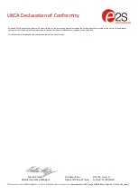
18-3) Header Pins Settings 


J1 Header Pin - Position A 
Factory default position (pins 1 & 2 not linked) 
Places TB1 Current Sense Resistor (CSR) in circuit. 
As used in 4 - Wire Configuration 


J1 Header Pin - Position B 
(pins 1 & 2 linked) 
Removes TB1 Current Sense Resistor (CSR) out of circuit. 

Figure 12: J1 Header pin positions 

 Current Sense Resistor (CSR) 


J2 Header Pin - Position A 
Factory default position (pins 1 & 2 linked) 
Removes power supply terminal Fault Resistor (FR) & RLY 
1-2 out of circuit. 
As used in 4 -Wire Configuration 


J2 Header Pin - Position B 
(pins 2 & 3 linked)  
Places power supply terminal Fault resistor & RLY 1-2 in 
circuit. 
As used in 2 

 Wire Configuration 

Figure 13: J2 Header pin positions 

 Fault Resistor (FR) 


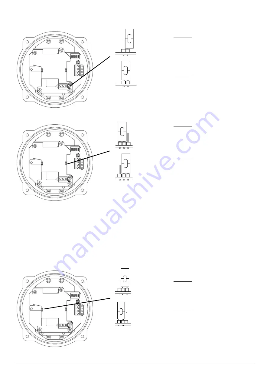
18-4) SIL 2 Hard Reset Function 

 
Power down the unit completely for a minimum of 30 seconds. Move the hard reset header pin (Jumper J3) to reset position B 
shown. Then power the unit for a minimum of 5 seconds. Power down the unit for 30 seconds and then move the header pin back to 
Position A. 
 
The unit has now been reset. 
 
If the hard reset process does not correct the latched fault the alarm horn sounder may require further investigation, please contact 
your local E2S representative. 


J3 Header Pin - Position A 
Factory default position (pins 2 & 3 linked) 
Hard Reset Function disabled 

 Normal Operation 


J3 Header Pin - Position B 
(pins 1 & 2 linked) 
Hard Reset Enabled - Active reset mode 

Figure 14: J3 Header pin positions 

 Hard Reset Function 

Summary of Contents for BExS110D-SIL

Page 1: ...e table shows the input current taken by the various sounders The current levels shown above are for the 440Hz Continuous tone nominal input voltage Nominal current at nominal voltage Table 1 Electric...

Page 2: ...mixture likely to occur in normal operation Zone 2 Explosive gas air mixture not likely to occur in normal operation and if it does it will only exist for a short time Gas Groupings Group IIA Propane...

Page 3: ...ure and the O ring seal is in place When replacing the flameproof cover casting ensure that it is square with the flameproof chamber casting before inserting Carefully push the cover in place allowing...

Page 4: ...in the flameproof enclosure See section 7 of this manual for access to the flameproof enclosure Wires having a cross sectional area between 0 5 mm to 2 5mm can be connected to each terminal way If an...

Page 5: ...pattern generation and signal output checks Default Tone 1 0 0 0 0 0 0 ON 1 OFF 0 Figure 7 DIP switch configuration Refer to D210 95 651 IS Tone Table for tone selection Table 2 below is a summary of...

Page 6: ...ndby mode and Active mode Health status of power supply Sounder correct function and tone pattern The SIL 2 sounder operates as part of a SIL 2 system The sounder will after commissioning remain power...

Page 7: ...ase contact your local E2S representative Commissioning System Functional start up of System Normally in reverse polarity mode When Commissioning system the power must not be disrupted to the SIL 2 Un...

Page 8: ...sounder check on pattern generation and signal output checks Important Only tones use tones that are stated as SIL 2 approved for the SIL 2 application Ensure that the unit is set to one of these tone...

Page 9: ...he circuit Note a cable short circuit will not be detectable in this configuration For one unit only Sounder power supply terminal block Current drawn mA Active Mode 190mA Standby Mode 25mA SIL2 TB1 C...

Page 10: ...ts and faults occur If multiple SIL 2 alarm horn sounders are to be cabled in series the monitoring connections differ from that of a single alarm horn sounder For more information see manual D197 00...

Page 11: ...pins 2 3 linked Places power supply terminal Fault resistor RLY 1 2 in circuit As used in 2 Wire Configuration Figure 13 J2 Header pin positions Fault Resistor FR 18 4 SIL 2 Hard Reset Function Power...

Page 12: ...sound output despite no input BExS110D SIL Failure to Sound Integrity in respect of failure to release SIL 2 Total Failure rate 0 304 pmh hazardous failure rate revealed 0 233 pmh hazardous failure r...

Page 13: ...9 k CSR Current Sense Resistor is E 2 7 k EOL End Of Line resistor is F 3 3 k Two digit resistor coding on other units BExS110DFDC024AB1S1R AZ Where the FR Fault Resistor is A 2 2 k EOL End Of Line r...

Page 14: ...n over 0 5s Continuous 660Hz 1 1 0 0 1 0 2 5 Alternating 554 440Hz at 1Hz 0 0 1 0 1 0 2 5 Intermittent 554Hz at 0 875Hz 1 0 1 0 1 0 2 5 800Hz pulsing at 2Hz 0 1 1 0 1 0 6 5 Sweeping 800 1000Hz at 50Hz...

Page 15: ...e 1 ve Stage 1 ve For full 4 Wire SIL 2 Connection Monitor SIL 2 ve and SIL 2 ve Terminals 1 2 in RLY1 2 Two or Three Stage Configuration Config 1b Line Monitoring Common Positive Header pins set to n...

Page 16: ...oup Netherlands B V Utrechtseweg 310 6812 AR Arnhem Netherlands Quality Assurance Notification Module D SIRA 05 ATEX M342 Provisions fulfilled by the equipment II 2G Ex db IIB or IIC T4 Gb II 2G Ex db...

Page 17: ...are in accordance with the restriction of the use of hazardous substances in electrical and electronic equipment including amendment by Directive 2015 863 EU Regulation EC 1907 2006 Registration Evalu...

Page 18: ...duction process Module D Sira Certification Service Notified Body No 0518 Rake Lane Eccleston Chester CH4 9JN UK Quality Assurance Notification Module D CSAE 22UKQAN0046 Provisions fulfilled by the eq...

Page 19: ...and Place of Issue London 12 09 2022 UKCA Declaration of Conformity On behalf of European Safety Systems Ltd I declare that on the date the equipment accompanied by this declaration is placed on the...

Reviews:

Related manuals for BExS110D-SIL