background image


E2S Warning Signals

      Impress House, Mansell Road, Acton, London W3 7QH


www.e2s.com


Tel: +44 (0)208 743 8880


Document No. D210-00-651-IS


Issue 1


13-01-23


Sheet 6 of 13


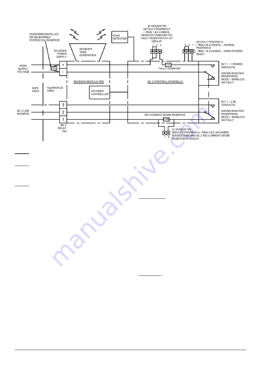
14)  SIL 2 Instruction/Safety Manual 


Figure 8 - The SIL 2 Module monitors the Sounder and interfaces to the customer plant. 


Warning


 To maintain the integrity of the SIL 2 units the system must be installed, commissioned and used within the parameters outlined in this 

manual. Failure to comply could result in an unintended unit operation or function. 


Warning


 The unit must be powered in either Standby or Active modes to comply with the SIL 2 approval requirement.  

If the power is disrupted the unit must be allowed to go through the commissioning cycle to reset.  
Failure to complete the commissioning cycle and continued disruption in the power supply will generate a fault state which will require the 
sounder to be reset (see section 18-4).  


Warning


 Only the alarm tones specified in section 17 may be selected for use in SIL2 compliant systems. 


SIL 2 System Description 


The SIL 2 module monitors the function of the device and 
provides feedback to the control panel. A fault condition can 
be communicated by two methods: 


4 wire installation can be seen as per section 18-1. 
A SIL 2 system wiring for fault detection in standby 
and active mode with independent fault contacts. 


2 wire installation can be seen as per section 18-2. 
A SIL 2 system by the introduction to the monitoring 
circuit and linking in an end of line resistor can only 
register the fault in standby mode. 


15)  SIL 2 System Terms and Function 

 
The SIL 2 Sounder Unit Monitors 


Standby mode and Active mode 


Health status of power supply 


Sounder correct function and tone pattern 


The SIL 2 sounder operates as part of a SIL 2 system. 
The sounder will after commissioning remain powered in 

Standby mode

 (reverse polarity) until the sounder is required 

to operate. When the signaling device is required to operate 
the polarity is changed to normal supply and the sounder will 
go into 

Active mode

 where it will start to sound the correct 

tone. When periodically testing the system and sounders 
operation is put into 

Active mode

 
The system panel or PLC will control whether the system is in 
either of the main two operational modes. 

Standby Mode


 This is where the power supply polarity is 

reversed so negative (

ve) is feed to the positive (+) sounder 

terminal and positive (+) is feed to the negative (

ve) sounder 

terminal. 
 
In Standby mode the sounder will not sound the tone but the 
SIL 2 unit is monitoring power supply and is set-up ready to 
go to Active (alarm) mode. 
 
Power relay RLY1-1 will be open whilst SIL 2 relay RLY1-2 
will be closed contact between terminals 1 & 2. 
 
If power is disrupted the SIL 2 unit will go into 

Fault mode

, in 

fault mode the Power relay RLY1-1 will close whilst SIL 2 
relay RLY1-2 will become open circuit between terminals 1 & 
2. 
 

Active Mode


 This is where the power is in normal polarity, 

positive (+) supplied to the positive (+) sounder terminal and 
negative (

ve) is supplied to the negative (

ve) sounder 

terminal. 
 
In Active mode the alarm horn sounder will output the 
selected alarm tone. The SIL 2 module checks for the correct 
alarm tone output and the functionality of the alarm tone 
signal generation process. 
 
Power relay RLY1-1 will be open whilst SIL 2 relay RLY1-2 
will be closed contact between terminals 1 & 2. 
 
The SIL 2 unit will also check for signal polarity. 


J3 HEADER PIN 


Summary of Contents for BExS110D-SIL

Page 1: ...e table shows the input current taken by the various sounders The current levels shown above are for the 440Hz Continuous tone nominal input voltage Nominal current at nominal voltage Table 1 Electric...

Page 2: ...mixture likely to occur in normal operation Zone 2 Explosive gas air mixture not likely to occur in normal operation and if it does it will only exist for a short time Gas Groupings Group IIA Propane...

Page 3: ...ure and the O ring seal is in place When replacing the flameproof cover casting ensure that it is square with the flameproof chamber casting before inserting Carefully push the cover in place allowing...

Page 4: ...in the flameproof enclosure See section 7 of this manual for access to the flameproof enclosure Wires having a cross sectional area between 0 5 mm to 2 5mm can be connected to each terminal way If an...

Page 5: ...pattern generation and signal output checks Default Tone 1 0 0 0 0 0 0 ON 1 OFF 0 Figure 7 DIP switch configuration Refer to D210 95 651 IS Tone Table for tone selection Table 2 below is a summary of...

Page 6: ...ndby mode and Active mode Health status of power supply Sounder correct function and tone pattern The SIL 2 sounder operates as part of a SIL 2 system The sounder will after commissioning remain power...

Page 7: ...ase contact your local E2S representative Commissioning System Functional start up of System Normally in reverse polarity mode When Commissioning system the power must not be disrupted to the SIL 2 Un...

Page 8: ...sounder check on pattern generation and signal output checks Important Only tones use tones that are stated as SIL 2 approved for the SIL 2 application Ensure that the unit is set to one of these tone...

Page 9: ...he circuit Note a cable short circuit will not be detectable in this configuration For one unit only Sounder power supply terminal block Current drawn mA Active Mode 190mA Standby Mode 25mA SIL2 TB1 C...

Page 10: ...ts and faults occur If multiple SIL 2 alarm horn sounders are to be cabled in series the monitoring connections differ from that of a single alarm horn sounder For more information see manual D197 00...

Page 11: ...pins 2 3 linked Places power supply terminal Fault resistor RLY 1 2 in circuit As used in 2 Wire Configuration Figure 13 J2 Header pin positions Fault Resistor FR 18 4 SIL 2 Hard Reset Function Power...

Page 12: ...sound output despite no input BExS110D SIL Failure to Sound Integrity in respect of failure to release SIL 2 Total Failure rate 0 304 pmh hazardous failure rate revealed 0 233 pmh hazardous failure r...

Page 13: ...9 k CSR Current Sense Resistor is E 2 7 k EOL End Of Line resistor is F 3 3 k Two digit resistor coding on other units BExS110DFDC024AB1S1R AZ Where the FR Fault Resistor is A 2 2 k EOL End Of Line r...

Page 14: ...n over 0 5s Continuous 660Hz 1 1 0 0 1 0 2 5 Alternating 554 440Hz at 1Hz 0 0 1 0 1 0 2 5 Intermittent 554Hz at 0 875Hz 1 0 1 0 1 0 2 5 800Hz pulsing at 2Hz 0 1 1 0 1 0 6 5 Sweeping 800 1000Hz at 50Hz...

Page 15: ...e 1 ve Stage 1 ve For full 4 Wire SIL 2 Connection Monitor SIL 2 ve and SIL 2 ve Terminals 1 2 in RLY1 2 Two or Three Stage Configuration Config 1b Line Monitoring Common Positive Header pins set to n...

Page 16: ...oup Netherlands B V Utrechtseweg 310 6812 AR Arnhem Netherlands Quality Assurance Notification Module D SIRA 05 ATEX M342 Provisions fulfilled by the equipment II 2G Ex db IIB or IIC T4 Gb II 2G Ex db...

Page 17: ...are in accordance with the restriction of the use of hazardous substances in electrical and electronic equipment including amendment by Directive 2015 863 EU Regulation EC 1907 2006 Registration Evalu...

Page 18: ...duction process Module D Sira Certification Service Notified Body No 0518 Rake Lane Eccleston Chester CH4 9JN UK Quality Assurance Notification Module D CSAE 22UKQAN0046 Provisions fulfilled by the eq...

Page 19: ...and Place of Issue London 12 09 2022 UKCA Declaration of Conformity On behalf of European Safety Systems Ltd I declare that on the date the equipment accompanied by this declaration is placed on the...

Reviews: