background image


E2S Warning Signals

      Impress House, Mansell Road, Acton, London W3 7QH


www.e2s.com


Tel: +44 (0)208 743 8880


Document No. D210-00-651-IS


Issue 1


13-01-23


Sheet 9 of 13


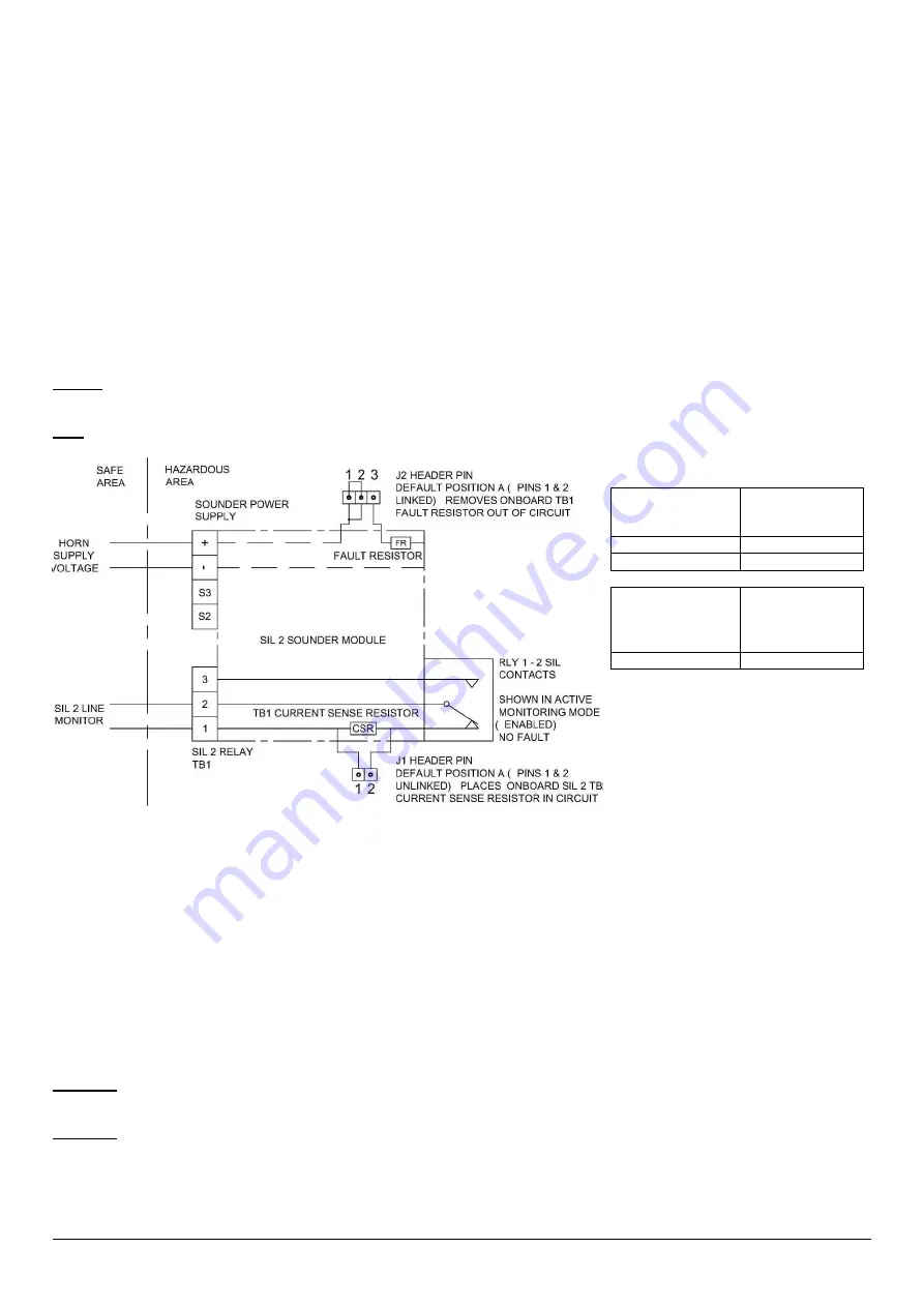
18-1) SIL 2 system wiring for fault detection in standby and active mode 

 4 wire installation 

(Recommended)


The customer is required to wire into both the sounder power supply terminals block and also the SIL 2 Relay terminals TB1  
 
The power supply terminals only need to have the supply power connected. This will be reverse polarity for monitoring mode and 
normal polarity for active mode. There is no need to fit an EOL resistor on the power supply terminal block as the TB1 is configured 
to raise a fault alarm in any situation. 
 
Terminal block TB1 is the output from the SIL 2 monitoring relay. Relay RLY 1-2 provides a closed circuit between TB1 terminals 1 & 
2 whilst powered. On detection of a fault event this will become open circuit. 
 
The fault will be seen via the SIL 2 TB1 terminals as soon as the fault occurs in either Active or Standby modes. 
 
When no fault is detected the circuit to the SIL 2 TB1 terminals 1 & 2 will include a factory fitted 3.3K Ohm current sense resistor 
(CSR) in series. When the circuit is driven with 24Vdc the detection current seen is ~7.3mA @ 24V. 
 
The only other fault mode is if the cable goes short circuit where a short will be seen by the panel.  
 

Option:

 Should the fault event output of RLY1-2 be required to operate as a switch, header J1 can be set to link pins 1 & 2 (see 

figure 10) thereby removing the 3.3k Ohm current sense resistor (CSR) from the circuit. 
 

Note

: a cable short circuit will not be detectable in this configuration. 


For one unit only: 

Sounder power 
supply terminal 
block


Current  drawn 
(mA)


Active Mode 

190mA 

Standby Mode 

25mA 


SIL2 
TB1 Current 
Sense Resistor 
value


Current drawn 
(mA)


3.3kΩ


7.2mA 

On fault mode, current drops to 0 as 
circuit goes open. 

Figure 10 - Schematic of SIL 2 system wiring for fault detection in standby and active mode 

 4 wire installation. 


If multiple SIL 2 alarm horn sounders are to be cabled in series the monitoring connections differ from that of a single alarm horn 
sounder. For more information see manual D197-00-651-IS available from the E2S website. 


18-2) SIL 2 system wiring for fault detection in standby mode only 

 2 wire installation 

 
Cabling is required to the positive '+' and negative '-' power input terminals only.  Monitoring will occur in standby mode only whilst 
power supply polarity is reversed. An EOL resistor may be added during installation or can be factory fitted. See Table 3 for EOL 
resistor value guidance. 
 
The SIL2 monitoring module contains a factory fitted Power Supply Fault Resistor 2.2K Ohm (FR). When a fault is detected the Fault 
Resistor will activated. The total measurable resistance of the EOL resistor and Fault Resistor across the power terminals which 

already has customer EOL resistor (2.2kΩ) in place. This will result in a tota

l fault detection current of 41.8mA @ 24V but can only 

be detected when unit is in Standby Mode. 
 

Important

: - The 2 wire configuration will not warn of a fault whilst in Active mode. A fault will only be detectable in standby mode 

when power supply polarity is reversed. 
 

Important

: - The 2-wire configuration requires the J2 header pin to be set to position B (see figure 13). Factory default position is A. 

Summary of Contents for BExS110D-SIL

Page 1: ...e table shows the input current taken by the various sounders The current levels shown above are for the 440Hz Continuous tone nominal input voltage Nominal current at nominal voltage Table 1 Electric...

Page 2: ...mixture likely to occur in normal operation Zone 2 Explosive gas air mixture not likely to occur in normal operation and if it does it will only exist for a short time Gas Groupings Group IIA Propane...

Page 3: ...ure and the O ring seal is in place When replacing the flameproof cover casting ensure that it is square with the flameproof chamber casting before inserting Carefully push the cover in place allowing...

Page 4: ...in the flameproof enclosure See section 7 of this manual for access to the flameproof enclosure Wires having a cross sectional area between 0 5 mm to 2 5mm can be connected to each terminal way If an...

Page 5: ...pattern generation and signal output checks Default Tone 1 0 0 0 0 0 0 ON 1 OFF 0 Figure 7 DIP switch configuration Refer to D210 95 651 IS Tone Table for tone selection Table 2 below is a summary of...

Page 6: ...ndby mode and Active mode Health status of power supply Sounder correct function and tone pattern The SIL 2 sounder operates as part of a SIL 2 system The sounder will after commissioning remain power...

Page 7: ...ase contact your local E2S representative Commissioning System Functional start up of System Normally in reverse polarity mode When Commissioning system the power must not be disrupted to the SIL 2 Un...

Page 8: ...sounder check on pattern generation and signal output checks Important Only tones use tones that are stated as SIL 2 approved for the SIL 2 application Ensure that the unit is set to one of these tone...

Page 9: ...he circuit Note a cable short circuit will not be detectable in this configuration For one unit only Sounder power supply terminal block Current drawn mA Active Mode 190mA Standby Mode 25mA SIL2 TB1 C...

Page 10: ...ts and faults occur If multiple SIL 2 alarm horn sounders are to be cabled in series the monitoring connections differ from that of a single alarm horn sounder For more information see manual D197 00...

Page 11: ...pins 2 3 linked Places power supply terminal Fault resistor RLY 1 2 in circuit As used in 2 Wire Configuration Figure 13 J2 Header pin positions Fault Resistor FR 18 4 SIL 2 Hard Reset Function Power...

Page 12: ...sound output despite no input BExS110D SIL Failure to Sound Integrity in respect of failure to release SIL 2 Total Failure rate 0 304 pmh hazardous failure rate revealed 0 233 pmh hazardous failure r...

Page 13: ...9 k CSR Current Sense Resistor is E 2 7 k EOL End Of Line resistor is F 3 3 k Two digit resistor coding on other units BExS110DFDC024AB1S1R AZ Where the FR Fault Resistor is A 2 2 k EOL End Of Line r...

Page 14: ...n over 0 5s Continuous 660Hz 1 1 0 0 1 0 2 5 Alternating 554 440Hz at 1Hz 0 0 1 0 1 0 2 5 Intermittent 554Hz at 0 875Hz 1 0 1 0 1 0 2 5 800Hz pulsing at 2Hz 0 1 1 0 1 0 6 5 Sweeping 800 1000Hz at 50Hz...

Page 15: ...e 1 ve Stage 1 ve For full 4 Wire SIL 2 Connection Monitor SIL 2 ve and SIL 2 ve Terminals 1 2 in RLY1 2 Two or Three Stage Configuration Config 1b Line Monitoring Common Positive Header pins set to n...

Page 16: ...oup Netherlands B V Utrechtseweg 310 6812 AR Arnhem Netherlands Quality Assurance Notification Module D SIRA 05 ATEX M342 Provisions fulfilled by the equipment II 2G Ex db IIB or IIC T4 Gb II 2G Ex db...

Page 17: ...are in accordance with the restriction of the use of hazardous substances in electrical and electronic equipment including amendment by Directive 2015 863 EU Regulation EC 1907 2006 Registration Evalu...

Page 18: ...duction process Module D Sira Certification Service Notified Body No 0518 Rake Lane Eccleston Chester CH4 9JN UK Quality Assurance Notification Module D CSAE 22UKQAN0046 Provisions fulfilled by the eq...

Page 19: ...and Place of Issue London 12 09 2022 UKCA Declaration of Conformity On behalf of European Safety Systems Ltd I declare that on the date the equipment accompanied by this declaration is placed on the...

Reviews: