European Safety Systems Ltd.
Impress House, Mansell Road, Acton, London W3 7QH
www.e2s.com
Tel: +44 (0)208 743 8880
Document No. D199-00-201-IS
Issue 4
07-10-21
Sheet 5 of 7
NEC Class / Zone, CEC Class / Zone, and NEC & CEC Class
/ Division installation standards:
National Electrical Code, NFPA 70 or CSA 22.1 Canadian
Electrical Code, Part I, Safety Standard for Electrical
Installations, Section 32.
The installation of the units must also be in accordance with
any local codes that may apply and should only be carried out
by a competent electrical engineer who has the necessary
training.
7.2. Cable Selection and Connections
When selecting the cable size, consideration must be given to
the input current that each unit draws (see table 1), the number
of beacons on the line and the length of the cable runs. The
cable size selected must have the necessary capacity to
provide the input current to all of the beacons connected to the
line.
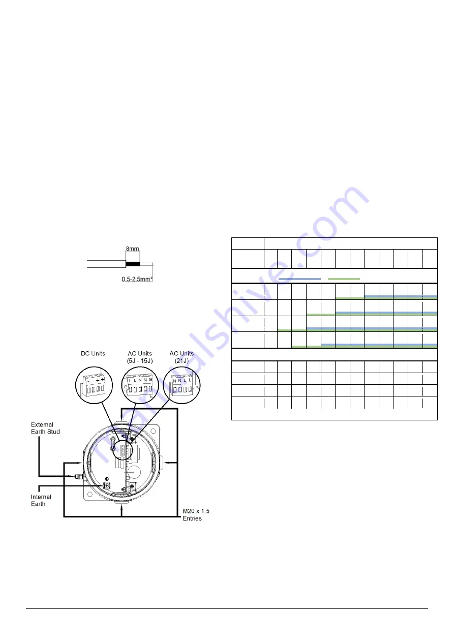
Electrical connections are to be made into the terminal blocks
on the PCBA, using solid wire 0.5-4mm2 / AWG 20-12 or
stranded wire, sizes 0.5-2.5mm2 / AWG 24-14. Wire insulation
needs to be stripped 8mm. Wires may be fitted securely with
crimped ferrules.
Figure 4: Wire Preparation.
Terminal screws need to be tightened down with a tightening
torque of 0.45 Nm / 5 Lb-in. A 5-way terminal block is provided
on the AC Beacon: 2-off Live, 2-off Neutral and 1-off Earth
terminals in total. A 4-way terminal block is provided on the DC
Beacon: 2-off +ve and 2-off -ve terminals.
Figure 5: STExB2 Entries and Terminal Block Location.
When connecting wires to the terminals great care should be
taken to dress the wires so that when the cover is inserted into
the chamber the wires do not exert excess pressure on the
terminal blocks. This is particularly important when using
cables with large cross-sectional areas such as 2.5mm².
Earthing
Internal earthing connections should be made to the Internal
Earth terminal in the base of the housing using a ring crimp
terminal to secure the earth conductor under the earth clamp.
The earth conductor should be at least equal in size and rating
to the incoming power conductors.
External earthing connections should be made to the M5 earth
stud, using a ring crimp terminal to secure the earth conductor
to the earth stud. The external earth conductor should be at
least 4mm2 in size.
7.3. Cable Glands, Blanking Elements & Adapters
For high ambient temperatures, the cable entry and the cable
branching point temperatures may exceed the following
temperatures:
•
For ATEX / IECEx: 70ºC at entry or 80ºC at branching point.
•
For NEC / CEC: 60ºC at entry or 60ºC at branching point.
Therefore, suitable heat resisting cables and cable glands
must be used, with a rated service temperature at least as
stated in the table below:
Max Ambient Temperature (ºC)
Model
GNExB2
15 20
25
30
35
40
45
50
55
60
65 70
ATEX / IECEx / NEC / CEC Approved
X05DC
62
67
72
77
82
87 92
X05AC
64
69
74
79
84
89
94
99 104
X10DC
61
66
71
76
81
86
91
96 101 106 111
X10AC
62
67
72
77
82
87
92
97 102 107
ATEX / IECEx Approved
X15DC
72
77
82
87
92
97 102 107 112 117 122
X15AC
74
79
84
89
94
99 104 109
X21DC
72
77
82
87
92
97 102 107 112 117 122
X21AC
73 78
83
88
93
98 103 108 113 118 123 128
Table 2: Min. Ratings of Cables & Cable Glands.
Cable Glands
The cable gland entries have an M20 x 1.5 entry thread. Only
use suitably rated and certified cable glands, as per type of
approval, which must be suitable for the type of cable being
used and also meet the requirements of the current flameproof
installation standards (see section 7.1).
Blanking Plugs
When only one cable entry is used the other entries must be
closed with suitably rated and certified blanking plugs as per
type of approval.
Any unused cable entries must be closed with suitably rated
and certified blanking plugs.


