AVIIVA® EM2-EM4
26
1013D - AVIIVA EM2/EM4 02/11
e2v semiconductors SAS 2011
•
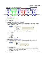
Output mode
(
OutputMode
) :
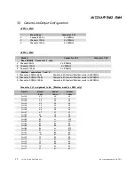
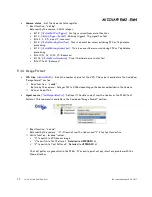
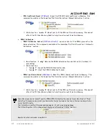
Set the CameraLink Output mode (refer to Chap 3.2.3 : CameraLink
Output Configuration). This command is available in the CommCam “Image Format” section :
Read function : “
r mode
”;
Returned by the camera : Output mode from 0 to 5 (see below). Values from 0 to 2 are reserved for
EM4 only.
Write function : “
w mode
” <value> :
detailed in the table below :
Modes
Connector CL1
Connector CL2
Mode value
Base 40Mhz (EM2) or 80MHz (EM4)
2 Channels interlaced 8bits
2 x 40MHz or 80Mhz 8 bits
-
3
2 Channels interlaced 10bits
2 x 40MHz or 80Mhz 10 bits
-
4
2 Channels interlaced 12bits
2 x 40MHz or 80Mhz 12 bits
-
5
Medium 40MHz (EM4 only)
4 Channels x 40MHz 8bits
CameraLink Standard Medium mode in 4x40MHz
0
4 Channels x 40MHz 10bits
CameraLink Standard Medium mode in 4x40MHz
1
4 Channels x 40MHz 12bits
CameraLink Standard Medium mode in 4x40MHz
2
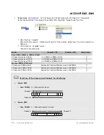
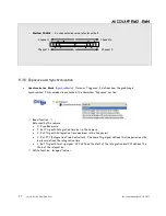
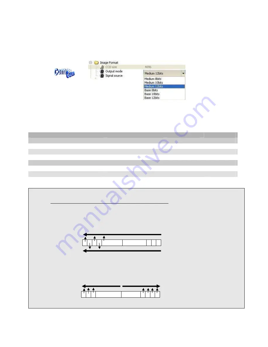
Structure of the Camera Link Channels for interfacing
Camera EM2
o
Base 40MHz :
2 x Channels interlaced
Camera EM4
o
Base 80MHz :
2 x Channels separate diverge :
Channel 1
Channel 2
Channel 1
Channel 2

