U
SER
M
ANUAL
16
K
/8
K
CXP
M
ONO
–
R
EV
K
–
06/2017
P
A G E
|
23
Ratio 1 : Equivalent to x2 ratio between Top and Bottom or 1 bit in the Dynamic
Ratio 2 : Equivalent to x4 ratio between Top and Bottom or 2 bit in the Dynamic
Ratio 4 : Equivalent to x8 ratio between Top and Bottom or 3 bit in the Dynamic
Ratio 8 : Equivalent to x16 ratio between Top and Bottom or 4 bit in the Dynamic
How to Set the HDR Mode
Set The Sensor Mode in “HDR”
Set The HDR Mode in “Single Line HDR” to Output an HDR Line
Select the Ratio of exposure required between the low and the high level Lines.
Set the Camera Synchronization Mode in Full Exposure Mode Preset : The choice of the
exposure of the single Line is made in Automatic by selecting the Ratio between High
and Low Level Lines.
More details are given in Appendix C
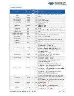
The following HDR Parameters are available only if the Sensor Mode is set to “HDR” :
HDR Mode
:
“0” : Output Single Line Bottom Only.
“1” : Output Single Line Top Only
“2” : Output HDR Line
HDR Ratio
:
“0” : Ratio 1 or x2 between LSB and MSB
“1” : Ratio 2 or x4 between LSB and MSB
“2” : Ratio 4 or x8 between LSB and MSB
“3” : Ratio 8 or x16 between LSB and MSB
7.2.5
Test Image Pattern Selector
This selection Defines if the data comes from the normal Sensor operation and FPGA Chain or from digital
patterns generated at the end of the FPGA. This is mainly useful to detect some interfacing or connection
issues.
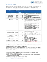
To switch to Cmos sensor image
Grey Horizontal Ramp (Fixed) :
See AppendixA
White Pattern (Uniform white image : 255 in 8Bits or 4095 in 12bits)
Grey Pattern (Uniform middle Grey : 128 in 8bits or 2048 in 12 bits)
Black Pattern (Uniform black : 0 in both 8 and 12 bits)
Grey vertical Ramp (moving)
When any of the Test pattern is enabled, the whole processing chain of the FPGA is disabled.

