background image

® 8k/4k CL Color 

13

e2v semiconductors SAS 2014

3.2.1


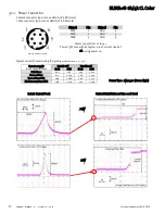
Power Connector 

Camera connector type: Hirose HR10A-7R-6PB (male) 
Cable connector type: Hirose HR10A-7P-6S (female) 


Camera side description


Signal 

Pin 

Signal 

Pin 

PWR 

GND 

PWR 

GND 

PWR 

GND 


Power supply from 12 to 24v 

Power 7,5W max with an typical inrush current peak of 

1A during power up 


Typical current/Power during the grab 

(possible variation : +/- 5%)


Power Time : Max 40s (Green Light) 


Inrush Current Peak 


Current Establishment time and level 


24V 


  12V 


Camera supply 

(Line Period Minimum)


Supply 12V 

Supply 24V 

I(mA) 

P(W) 

I(mA) 

P(W) 

Full 8Taps 

605 

7.26 

303 

7.272 

Deca 10Taps 

613 

7.356 

308 

7.392 

Base 3Taps RGB 

589 

7.068 

298 

7.152 

Medium 2x 3Taps RGB 

598 

7.176 

302 

7.248 

Summary of Contents for ELIIXA+ 8k/4k CL

Page 1: ...ELIIXA 8k 4k CL Cmos Multi Line Color Camera User Manual...

Page 2: ...Input output Connectors and LED 12 3 2 1 Power Connector 13 3 2 2 Status LED Behaviour 14 3 2 3 CameraLink Output Configuration 14 3 2 3 1 True Color Single or Enhanced 15 3 2 3 2 Full Definition Sin...

Page 3: ...Variable Exposure Time 43 8 2 Synchronisation Modes with Maximum Exposure Time 44 8 3 Timing Values 44 9 APPENDIX C CameraLink Data Cables 45 9 1 Choosing the Cable 45 9 2 Choosing the Data Rate 46 1...

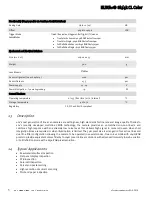
Page 4: ...on Low Power Consumption 9W F Mount compliance 1 2 Key Specifications Characteristics Typical Value Unit Sensor Characteristics at Maximum Pixel Rate Resolution 8192 or 4096 RGB Pixels pixel size squa...

Page 5: ...inition mode with a 8192 RGB pixel resolution 1 4 Typical Applications Raw material surface inspection Flat panel display inspection PCB inspection Solar cell inspection Parcel and postal sorting High...

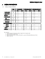
Page 6: ...lor 13650 13650 13650 SNR 3 4 Sat dB 40 40 40 Peak Response 460 530 660nm LSB 8bits nJ cm2 8 10 12 4 5 6 8 10 12 Non Linearity 0 3 0 3 0 3 Without Flat Field Correction FPN rms LSB 0 21 1 0 23 1 0 22...

Page 7: ...nly in the Full Definition Enhanced mode See Below 2 2 1 True Colour Enhanced Mode TCE 10 m pixels R G B Twice less pixels than B W Requires x3 2 the data flow of B W High Sensitivity True Color mode...

Page 8: ...tion of the aspect ratio of the image 2 2 3 Full Definition Single Mode FDS 5 m pixels R G B Same definition than B W Requires x3 the data flow of the B W Sensitivity is half of the TC mode available...

Page 9: ...low of the B W Sensitivity is the same as the TC mode available Equivalent to 6 x Pixels of 5 m with their respective colour filters Full Exposure control is activated in this mode as the Time Delay E...

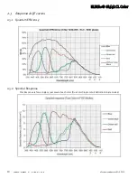
Page 10: ...Color 10 e2v semiconductors SAS 2014 2 3 Response QE curves 2 3 1 Quantum Efficiency 2 3 2 Spectral Response This Response is for a single 5x5 m pixel of each color True Color Single or Full Definiti...

Page 11: ...ELIIXA 8k 4k CL Color 11 e2v semiconductors SAS 2014 3 CAMERA HARDWARE INTERFACE 3 1 Mechanical Drawings The Step file is available on the web www e2v com cameras X Y Z...

Page 12: ...ensor alignment Z 10 3 mm 100 m X 9 5 mm 100 m Y 62 5mm 100 m Flatness 50 m Rotation X Y plan 0 15 Tilt versus lens mounting plane 50 m USB Connector For Firmware upgrade Power Connector 12 24V DC Mul...

Page 13: ...pply from 12 to 24v Power 7 5W max with an typical inrush current peak of 1A during power up Typical current Power during the grab possible variation 5 Power Time Max 40s Green Light Inrush Current Pe...

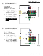
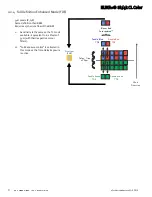
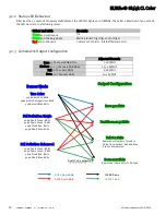
Page 14: ...3 x 85MHz Full 8 Channels 8bits 8 x 85MHz Deca 10 Channels 8bits 10 x 85MHz Sensor Mode True Color 4096 pixels Red 8bits 4096 pixels Average Green 8bits 4096 pixels Blue 8bits Full Definition Single 4...

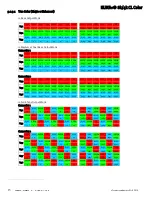
Page 15: ...EN GREEN GREEN GREEN GREEN 2049 2050 2051 2052 2053 2054 2055 2056 4091 4092 4093 4094 4095 4096 Tap6 BLUE BLUE BLUE BLUE BLUE BLUE BLUE BLUE BLUE BLUE BLUE BLUE BLUE BLUE 2049 2050 2051 2052 2053 205...

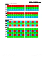
Page 16: ...UE RED GREEN BLUE RED 2 6 9 12 16 19 22 26 4079 4082 4086 4089 4092 4096 Tap7 RED GREEN BLUE RED GREEN BLUE RED GREEN BLUE RED GREEN BLUE RED GREEN 3 6 9 13 16 19 23 26 4079 4083 4086 4089 4093 4096 T...

Page 17: ...92 4093 4094 4095 4096 Connector 2 Tap4 GREEN GREEN GREEN GREEN GREEN GREEN GREEN GREEN GREEN GREEN GREEN GREEN GREEN GREEN 2049 2050 2051 2052 2053 2054 2055 2056 4091 4092 4093 4094 4095 4096 Tap5 B...

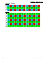
Page 18: ...ED BLUE RED BLUE RED BLUE RED BLUE RED BLUE RED 3277 3278 3279 3280 3281 3282 3283 3284 4909 4910 4911 4912 4913 4914 Tap6 GREEN GREEN GREEN GREEN GREEN GREEN GREEN GREEN GREEN GREEN GREEN GREEN GREEN...

Page 19: ...nterferencethat may cause undesired operation This equipmenthas been tested and found to comply with the limits for Class A digital device pursuant to part 15 of the FCC rules These limits are designe...

Page 20: ...ELIIXA 8k 4k CL Color 20 e2v semiconductors SAS 2014...

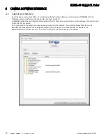
Page 21: ...with the Camera Both User Manual this document and CommCam control software have to be downloaded from the web site This ensure you to have an up to date version Main Camera page www e2v com cameras O...

Page 22: ...GenICam standard COMMCAM recognizes and detects automatically all the UCL Cameras connected on any transport layers Camera Link or COM ports of your system Once connected to the Camera you have an eas...

Page 23: ...received before sending a new command The camera return code has to be received before sending a new command Some commands are longer than the others Waiting for the return code ensure a good treatme...

Page 24: ...ersion Get Camera Hardware version Read function r dhwv Returned by the camera String of 32 bytes including 0 Can not be written Device Firmware Version DeviceFirmwareVersion Get camera synthetic firm...

Page 25: ...ower dissipation drops down to about 6W During the standby mode the grab is stopped Once the Standby mode turned off the Camera recovers in less than 1ms to send images again from the sensor Camera st...

Page 26: ...ommand in xml Value always 1 Output mode OutputMode Set the CameraLink Output mode refer also to Chapter CameraLink Output Configuration This command is available in the CommCam Image Format Control s...

Page 27: ...ck the color buffer FULL Mode 8 Taps Separate outputted from Left to Right 8x1536 pixels each Channel in True Color Mode 12290 pixels total 4096 Green 4096 Red and 4096 Blue pixels 8x2048 pixels each...

Page 28: ...re on the Four Color lines normally the variation of the Exposure time should not possible in this sensor mode Thanks to an e2v licensed solution two of the Exposure controlled mode Ext Trig with inte...

Page 29: ...ilable in the CommCam Image Format section Read function r srce Returned by the camera 0 if Source from the Sensor and 1 to 5 if test pattern active Write function w srce value 0 To switch to CCD sens...

Page 30: ...function w sync value The Timing diagrams associated to each Synchronization mode and the Timing values associated are detailed in the APPENDIX B of this document Exposure time ExposureTime Defines t...

Page 31: ...ation Gain This command is available in the CommCam Gain Offset section Read function r pamp Returned by the camera Integer corresponding to one of the 3 different step values 0 x1 0dB 1 x2 6dB 2 x4 1...

Page 32: ...fs int Tap Balance Gains Enable Switch TapBalanceGainEnable Read function r fgae Returns the Tap Balance Status Write function w fgae val with val 0 or 1 0 Disables the Tap Balance Gains 1 Enables the...

Page 33: ...n r gwbg Returned by the camera Integer value from 0 to 1548 The corresponding Gain is calculated as 20 log 1 val 1024 in dB Write function w gwbg val Digital GreenBlue Gain Gain with GainSelector Dig...

Page 34: ...Offset on 8 bits Signed Int 5 3 They cover a dynamic of 16LSB in 12bits with a resolution of 1 8 LSB 12bits o A Gain on 12 bits with a max gain value of x5 Gain U12 1 Gain 1024 x1 to x3 999 by step of...

Page 35: ...or the FFC adjust and enable it White uniform moving target Launch the FFC Enable the FFC You can save the FFC result both FPN PRNU in the same time in one of the x4 FFC User Banks The user target and...

Page 36: ...is doesn t affect the FFC User Memory Bank but only the active coefficients in Memory PRNU Calibration o PRNU Calibration Control FFCCalibrationCtrl Launch or abort of the PRNU process for the Gains c...

Page 37: ...for red pixels Coefficient from address 4096 to 8191 are for blue pixels Coefficient from address 8192 to 12287 are for greenRed pixels Coefficient from address 12288 to 163837 are for greenBlue pixel...

Page 38: ...nk in the current FFC Read function r rffc Get the current FFC Bank used Returned by the camera 0 for Factory bank or 1 to 4 for User banks Write function w rffc val Bank val 1 to 4 for User banks Not...

Page 39: ...d deviation of all the Red pixel level values of Region of interest Read function r pstr Get the standard deviation Returned by the camera Unsigned format value U12 4 o Pixel Min value RedPixelROIMin...

Page 40: ...el values of Region of interest Read function r pstj Get the standard deviation Returned by the camera Unsigned format value U12 4 o Pixel Min value Green b PixelROIMin Minimum GreenBlue level pixel v...

Page 41: ...amera can be saved in 4 different User banks and one Integrator bank This setting includes also the FFC and LUT enable This function is available in the Save Restore Settings section Load settings fro...

Page 42: ...est pattern 1 is a vertical moving wave each new line will increment of 1 gray level in regards with the previous one level reaches 255 before switching down to 0 7 2 Test Pattern 2 Fixed Horizontal R...

Page 43: ...nalog Gain is applied by the gradient of the counting ramp see next chapter Gain Offset The conversion time depends on the pixel format 8 or 10 bits 6 s This conversion is done in masked time eventual...

Page 44: ...ective Exposure Time will be about Tintreal Tint Tx Td 8 2 Synchronisation Modes with Maximum Exposure Time In these modes the rising edge of the Trigger internal or External starts the readout proces...

Page 45: ...en for a dedicated maximum value per meter of cable as max 50ps m The CameraLink Standards defines the maximum total skew possible for each data rate Here is a following example of cable and the cable...

Page 46: ...Max kHz Tper Min s Line Rate Max kHz Tper Min s True Color 4k 10 m 17 6 56 7 35 2 28 4 46 5 21 5 58 1 17 2 Full Def 8K 5 m 8 8 113 4 17 6 56 7 26 38 4 44 22 7 Data Frequency 70MHz Sensor Mode Base 3x8...

Page 47: ...ELIIXA 8k 4k CL Color 47 e2v semiconductors SAS 2014 10 APPENDIX D Lens Mounts 10 1 F Mount F Mount Kit10 Part number EV71KFPAVIVA ABA...

Page 48: ...ELIIXA 8k 4k CL Color 48 e2v semiconductors SAS 2014 10 2 T2 M42x1 Mounts M42x0 75 T2 Mount Kit30 Part number AT71KFPAVIVA AKA M42x1 Mount Kit40 Part number AT71KFPAVIVA ADA...

Page 49: ...p for the connection issues Camera Power up 43s No LED Red Blinking Green Fixed Green Hardware failure or Firmware loading defect Contact Hotline for RMA If CommCam connection possible then the LED is...

Page 50: ...sensor mode to Full Definition single w smod 2 Set sensor mode to Full Definition Enhanced w smod 3 Set sensor mode to True Color Single ScanDirection r scdi Get scan direction w scdi 0 Set scan dire...

Page 51: ...l r pamp Get the current pre amp gain w pamp val Set pre amplifier gain to 0 12dB 1 6dB 2 0dB analog gain Change balances and compensation Gain GainSelector gainAll r gain Get current digital gain w g...

Page 52: ...are for blue pixels Coefficient from address 8192 to 12287 are for greenRed pixels Coefficient from address 12288 to 163837 are for greenBlue pixels FFCCalibrationCtrl r calg Get the PRNU calibration...

Page 53: ...1 reverse StatusErrorHardware Bit 16 true if hardware error detected 12 8 Communication Feature Commands Description ComBaudRate r baud Get current baud rate This feature is not saved in camera w baud...

Page 54: ...Green r PixelROIStandardDeviation r pstg Get ROI Stand deviation for GreenRed Pixels format U12 4 Green r PixelROIMin r pmig Get ROI Min value for GreenRed Pixels format U12 4 Green r PixelROIMax r pm...

Page 55: ...anual Revision Comments Details Firmware version 1st CommCam compliant Version Rev A First release 1 0 3 2 2 1 Rev B Update Firmware 1 1 0 2 3 1 Rev C True Color Single Change Documentation Template 1...

Page 56: ...ELIIXA 8k 4k CL Color 56 e2v semiconductors SAS 2014 Contact us online at e2v com imaging...

Reviews: