


W
AA
S
R
T
TO FIT 4BA
TERMINALS
LEADS Z LONG
SEE NOTE 11
SEE NOTE 2
SEE NOTE 10
REFERENCE
PLANE A
N
M
L
K
Y
J
G
E
F
Q
P
B
A
1
H
REFERENCE PLANE C
SEE NOTE 5
SURFACE A
SEE NOTES 2, 3 AND 4
2 HOLES
1
D
SEE NOTE 6
REFERENCE PLANE B
SEE NOTE 9
4 HOLES
1
C
SEE NOTE 8
SEE NOTE 7
SEE NOTE 1
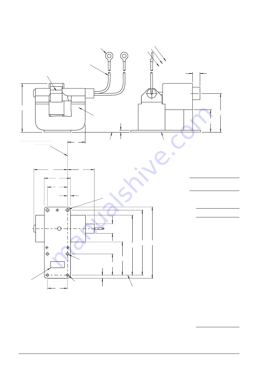
7936
OUTLINE
(All dimensions without limits are nominal)
Lead Connections
Colour
Element
Green
Heater
Yellow
Heater, cathode
Ref
Millimetres
A
113.11
+
0.38
B
104.22
+
0.10
C
4.318
+
0.076
D
4.445
+
0.076
E
4.368
+
0.41
F
32.5
+
0.1
G
31.0
+
0.1
H
25.4 max
J
5.18
+
0.38
K
41.28
+
0.41
L
52.4 max
M
55.55 max
N
30.15 max
P
101.6 max
Q
46.0 min
R
84.12 max
S
63.5
T
12.7 max
W
3.175
Y
30.99
+
0.10
Z
311.2
+
12.7
AA
33.0
MG5239T, page 4
#
e2v technologies


