switching the waveguide switch. If the N6143 control unit is used, an audible alarm
will activate indicating the fault condition to the operator.
The amplifiers will remain in the automatic mode as before. If the faulty amplifier
does not recover, a fault on the second amplifier will not result in switching of the
waveguide switch.
The waveguide switch coil should be a 24 V type and a tell back switch within the
waveguide switch should be configured so that each amplifier knows if it is
connected to the antenna.
Switching time is dependent upon the waveguide switch selected but will be typically
50 to 100 ms.
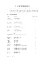
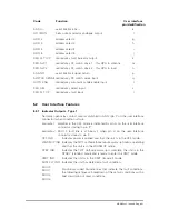
The interface between the control unit and the amplifiers is via the local serial
communications bus. As the amplifiers do not contain a transmitter/receiver
termination, the local serial communications bus should be fitted with 120
O
terminating impedances. This should be done within the control connector backshell
of the amplifier furthest from the N6143 control unit. 120
O +
1%,
1
/
4
W carbon film
or similar resistors should be fitted between pin d (Rx+) and pin e (Rx
7
), also
between pin b (Tx+) and pin c (Tx
7
) of the 41-pin amplifier control connector.
Termination of the serial communications bus is dependent upon the length and type
of cable used, and should follow normal transmission line practice.
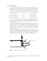
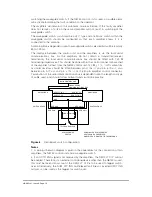
Figure 6
Redundant switch configuration
Notes
1. A wiring schematic diagram is given in the appendices for the connection of two
amplifiers, the N6143 control unit and a waveguide switch.
2. If an AUTO ENA signal is not received by the amplifiers, the RED FLT O/P will not
be enabled. Therefore, if an external controlling device other than the N6143 is used,
this must be taken into account if the RED FLT O/P is to be used to trigger switch-
over. Alternatively, the SUM FLT IND multiplexed fault lines or inverted XMIT IND
outputs can be used as the trigger for switch-over.
N6143 CONTROL UNIT
AMPLIFIER A
AMPLIFIER B
RED FLT O/P
RED FLT I/P
GND
RED FLT I/P
RED FLT O/P
GND
RED SW2
RED SW1
RED SW1
RED SW2
SWITCH SENSE
SWITCH SENSE
COIL B
COIL A
TELL BACK SWITCH
RF WAVEGUIDE
SWITCH
LOCAL SERIAL
COMMUNICATIONS BUS
"
SHOWN WITH RF WAVEGUIDE
SWITCH COIL A ENERGISED.
AMPLIFIER A IS ROUTED TO THE ANTENNA
HBN63xx-1, Issue 8, Page 16

