5
USER INTERFACES
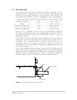
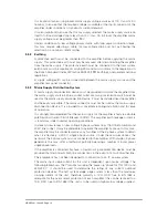
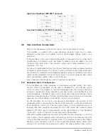
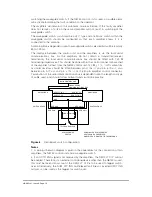
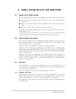
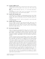
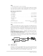
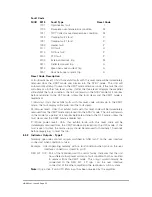
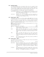
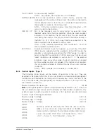
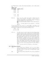
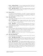
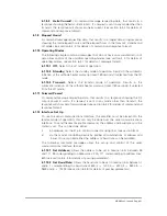
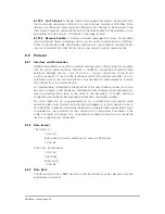
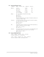
The amplifier is provided with two interfaces that are used to control the amplifier:
the user port and the serial communications interface (RS-485). All interfaces are
available on the 41-pin control connector, located next to the mains supply
connector. This section identifies each control connector pin and describes the
function of each pin, including the electrical specification.
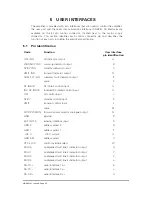
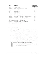
5.1
Pin Identification
Code
Function
User interface
pin identification
OFF IND
off indicator output
A
WARMUP IND
warm-up indicator output
B
STBY IND
standby indicator output
C
XMIT IND
transmit indicator output
D
SUM FLT IND
summary fault indicator output
E
spare
F
RF INHIB
RF inhibit control input
G
INV RF INHIB
inverted RF inhibit control input
H
OFF
off control input
J
STBY
standby control input
K
XMIT
transmit control input
L
spare
M
FWD PW MON
forward power monitor analogue output
N
GND
ground
P
EXT INTLK
external interlock input
R
ADD 0
address select 0
S
ADD 1
address select 1
T
+15 V
+15 V output
U
ADD SEL
address select
V
CTRL O/R
control override select
W
MUX 0
multiplexed fault line 1 indicator output
X
MUX 1
multiplexed fault line 2 indicator output
Y
MUX 2
multiplexed fault line 3 indicator output
Z
MUX 3
multiplexed fault line 4 indicator output
a
RS TX+
serial interface Tx+
b
RS TX
7
serial interface Tx
7
c
RS RX+
serial interface Rx+
d
HBN63xx-1, Issue 8, Page 20

