background image

3534-MANUL-V01.00.03 HFCT1 Operating Manual 


12 August 2021 

Page 2 of 10 

2.


Preparations for Use 

2.1


Installation 

Installation requirements can vary but the HFCT allows for easy installation due to its non-invasive ability to 
clamp around a cable. The HFCT should only be installed by competent persons with the required work permits 
for  the  environment  of  the  installation.  This  document  offers  guidance  on  the  installation  procedure.  For 
assistance regarding installation, contact EA Technology. 

2.1.1


Pre-Connection/Disconnection Assessment 

A risk assessment should always be carried out dependant on the installation environment. HFCTs by nature 
will  be  installed  within  dangerous  locations  such  as  substations  and  these  should  have  their  own  risk 
assessments and procedures in place and must be followed. Certain environments such as installation within 
cable chambers on switchgear may require the system to be proven de-energised amongst other requirements, 
in case of doubt when installing contact the manufacturer. 

2.1.2


Connecting/Disconnecting the HFCT procedure 

A visual inspection for signs of damage to the HFCT and connecting cables is to be carried out. Connect the 
supplied HFCT cable to the measurement device as specified in the relevant equipment manual, push and twist 
the cable connector into the BNC on the HFCT until the cable is locked in place. To disconnect the HFCT, gently 
push  and  twist  before  pulling  the  BNC  connector  off.  The  HFCT  must  always  be  terminated  into  the 
measurement  device before clamping/unclamping the HFCT around a measurement  point, failure to  do so 
increases the risk of electric shock.  

2.1.3


HFCT Mounting Guidance 

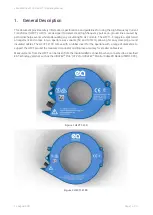
The  HFCT1-F50  and  HFCT1-F100  each  have  three  mounting  holes  that  can  be  utilised  for  permanent 
installations and secured using either cable ties or screws. Before installation, the best method for mounting 
the  HFCT  in  the  associated  environment  should  be  considered.  For  more  repeatable  readings  keeping  the 
conductor being measured central in the aperture of the HFCT is advised. The HFCT1-F100 comes with a rubber 
insert which can help when measuring smaller conductors down to 50mm, any smaller and the HFCT1-F50 
should be used in place of the HFCT1-F100. 


If permanent installation of HFCTs is being considered, contact Product Support for guidance notes. 


Summary of Contents for HFCT1

Page 1: ...MANUAL HFCT Operating Manual Model No HFCT1 Document Version V01 00 03 Date 12 August 2021...

Page 2: ...ission of the copyright holder EA Technology Ltd April 2021 EA Technology Limited Capenhurst Technology Park Capenhurst Chester CH1 6ES Tel 0151 339 4181 Fax 0151 347 2404 http www eatechnology com Re...

Page 3: ...installation this includes the ambient environment and building conditions along with other local hazards Local safety procedures and guidelines including the use of personal protective equipment mus...

Page 4: ...ual 12 August 2021 Page iii Contents 1 General Description 1 2 Preparations for Use 2 3 Maintenance 4 4 HFCT1 F50 Technical Specification 5 5 HFCT1 F100 Technical Specification 7 6 Sales and Service 9...

Page 5: ...ts The HFCT1 F range is a split toroid arrangement and comes in two aperture size variants 50 and 100mm allowing for easy clamping around insulated cables The HFCT1 F100 comes with a rubber insert for...

Page 6: ...FCT procedure A visual inspection for signs of damage to the HFCT and connecting cables is to be carried out Connect the supplied HFCT cable to the measurement device as specified in the relevant equi...

Page 7: ...ufacturer Connections can be made 1 By monitoring the earth cable only Figure 3 this is the preferred connection method 2 By monitoring the line conductor without the earth Figure 4 or 3 By monitoring...

Page 8: ...circuitry should be made If any doubt exists contact the manufacturer The HFCT can become damaged by dropping and care should be taken to ensure the HFCT is secured and handled correctly The core of t...

Page 9: ...10pC Nominal Accuracy 1V A Terminating impedance 50 Ohm Enclosure Insulation Rating CAT IV 150V 50Hz Response and Saturation Saturation Current at 50Hz 100 A 50Hz Frequency Response 70 dB Hardware Enc...

Page 10: ...nual 12 August 2021 Page 6 of 10 HFCT F50 Frequency Response Figure 7 HFCT1 F50 Response Curve 0 0 5 1 1 5 2 2 5 3 3 5 4 4 5 5 5 5 6 6 5 7 7 5 8 8 5 9 9 5 10 100 1000 10000 100000 Sensitivity V A Freq...

Page 11: ...0pC Nominal Accuracy 1V A Terminating impedance 50 Ohm Enclosure Insulation Rating CAT IV 150V 50Hz Response and Saturation Saturation Current at 50Hz 100 A 50Hz Frequency Response 70 dB Hardware Encl...

Page 12: ...T F100 Frequency Response Figure 8 HFCT1 F100 Response Curve HFCT Enclosure Dimensions HFCT1 F50 Dimensions HFCT1 F100 Dimensions 0 0 5 1 1 5 2 2 5 3 3 5 4 4 5 5 5 5 6 6 5 7 7 5 8 8 5 9 9 5 10 100 100...

Page 13: ...red by the Warranty Policy The following are not covered damage caused by accident misuse abuse product modification or neglect damage resulting from failure to follow instructions contained in your o...

Page 14: ...escribed in this document is in compliance with all applicable EU Directives and UK Statutory Instruments The full text of the EU and UK declarations of conformity are available at the following inter...

Page 15: ...Safer Stronger Smarter Networks EA Technology Limited Capenhurst Technology Park Capenhurst Chester CH1 6ES t 44 0 151 339 4181 e sales eatechnology com www eatechnology com...

Reviews: