ENGLISH 3
ENGLISH 4
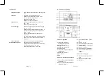
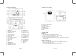
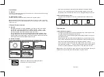
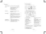
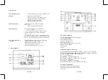
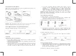
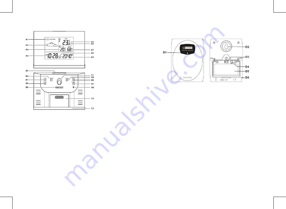
2. Main Unit Appearance
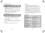
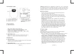
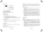
3. Outdoor Thermo Sensor
2.1 Part A- LCD
A1: Barometer Pressure Trend
A2: Weather Forecast
A3: Outdoor Temperature
A4: Indoor Temperature
A5: Time Display
A6: Outdoor Temperature Trend
A7: Indoor Humidity
A8: Day of Week
A9: Date
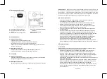
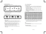
2.2 Part B- Buttons
B1: “ALARM ON/OFF” button
B2: “SNOOZE/LIGHT” button
B3: “MAX/MIN” button
B4: “-(C/F)” button
B5: “WEATHER” button
B6: “MODE/SET” button
B7: “+ (12/24)” button
B8: “CHANNEL” button
B9: “RESET” button
2.3 Part C- Structure
C1: Wall Mount Hole
C2: Battery Cover
C3: Stand
D1: Transmission Indication LED
D2: Wall Mount Hole
D3: Channel Select Switch
D4: “RESET” button
D5: Battery Compartment
D6: Stand
4. Getting Started:
4.1 Main Unit:
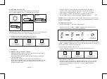
• Slide open main unit battery compartment cover [C2]
• Insert 3 x AAA batteries observing polarity [ “+” and “ –“ marks]
• Replace main unit battery compartment cover [C2]
• Use a pin to press the RESET [B9] button on the rear of the main unit, the main unit is
now ready for use
4.2 Outdoor Thermo Sensor
• Batteries compartment (D5) of thermo sensor is locating behind the back cover,
unscrews the batteries cover to open.
• Insert 2 x AAA batteries observing polarity [ “+” and “–“ marks]


