DB4020 Dual Band 40&20M SSB QRP Transceiver Kit
Page 19
P
in headers and jumpers
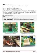
Place and solder the 5-pin header corresponding to the microphone and speaker.
Place and solder the pin headers “J1” and “J2”
Place and solder 4 pins strip on RX IF crystal filter input.
Place and solder 3 pins strip on RX IF crystal filter output
Place and solder 2 x female 15 pin strips for the Arduino UNO.
Turn the board over and use one hand to
insert and hold the header in place, using a “jumper” placed on
the header while you solder the pins to avoid burning your fingers. Use your other hand to hold the
soldering iron and move the board towards the solder to solder the headers in place. If you have
someone available to help you, it will be much easier!
Place jumpers on the terminals:
-
“
J1
”
if you do not use an ON/OFF switch.
-
“
J2
”
if you do not use the optional CW module.
-
“
RX IF Filter jumpers
”
if you no use the optional CW Interface and filter (see images)
Jumper on RX IF crystal filter input Jumper on RX IF crystal filter output


