DB4020 Dual Band 40&20M SSB QRP Transceiver Kit
Page 25
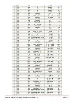
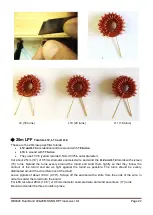
L12 (16 turns) L13 (17 turns) L14 (16 turns)
L6
T
oroid Transformer
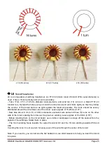
L6 is an impedance matching transformer. An FT37-43 (black toroid 9.5mm/0.375in outer diameter) is
used. It has a 10-turn primary and a 3-turn secondary.
-
Take 17cm (7.5”) of 0.5mm diameter enameled wire and wind ten (10) turns on a black FT37-43
toroidal core. Spread the turns evenly around the entire toroid and wind them tightly so that they follow
the contour of the toroid and are as tight against the toroid as possible. The turns should be evenly
distributed around the circumference of the toroid. Leave pigtails of 10-
20mm (0.70”).
- Now take about 8
cm (3.5”) of 0.5mm diameter enameled wire and wind three (3) turns on the other
side of the toroid, spacing the turns over the previous winding. Leave pigtails of 10-
20mm (0.70”).
- Before inserting them on the circuit board, use a knife or sandpaper to scrape off the enamel from the
pigtails of the windings. Solder them in place.
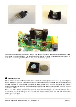
- The 3-turn winding faces towards the output transistor Q3 and the 10-turn winding towards C58 and
C66.
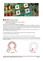
Counting the turns: Count one turn for every pass of the wire through the center of the toroid.
Note: If you need to, you can remove the Q2 heatsink or use small tweezers to help you insert the toroid
into place.


