DB4020 Dual Band 40&20M SSB QRP Transceiver Kit
Page 5
TIPS FOR BUILDERS WITH LITTLE EXPERIENCE
Tools required:
- Fine-tip soldering iron of about 30W, small wire cutters for cutting component leads, wire strippers,
long-nose pliers, needle-nose pliers, X-Acto knife, screwdriver for M3 screws, alignment tool for
adjusting IF transformers.
- You will need a good light and a magnifying glass to see the fine print on the components and other
assembly details.
Instruments required:
- Multimeter, frequency counter or HF receiver, RF power meter, dummy load of about 10W - 50ohms,
RF signal generator (desirable but not essential).
Soldering:
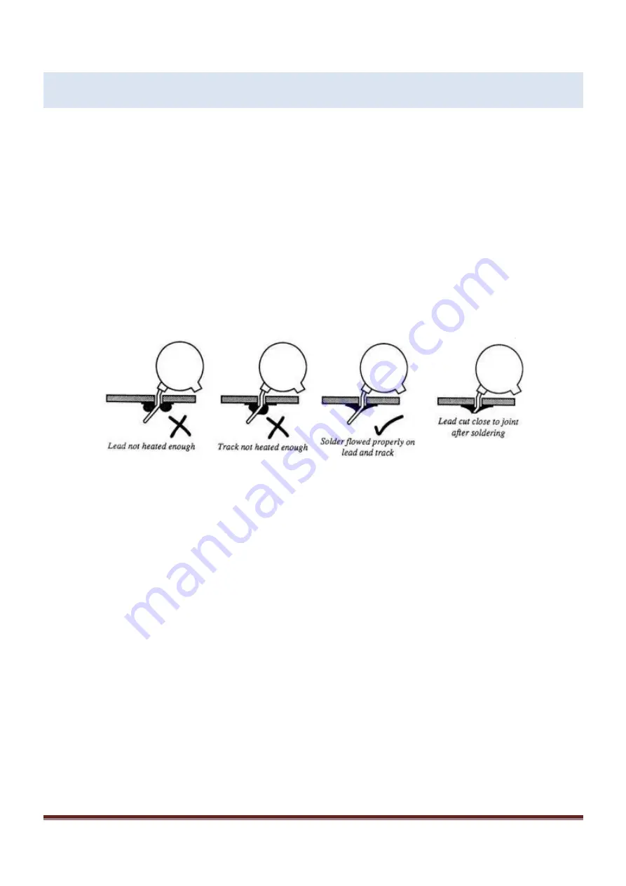
There are two essential things to keep in mind to ensure the proper functioning of a kit. The first is to put
the component into its proper place on the circuit board, the second is good soldering.
To solder properly, you must use a high-quality solder for electronics and the correct type of soldering
iron. Use a small soldering iron that has a fine, pointed tip. The soldering iron should be about 30 watts
(if it is not thermostatically controlled). Use only solder intended for electronic soldering; NEVER use
extra flux. You should hold the hot soldering iron in contact with both the circuit board and the
component lead for about two seconds to heat them up. Then, keeping the soldering iron in place, touch
the solder at the junction of the component lead and circuit board trace and wait about two seconds or so
until the solder flows between the lead and the trace to form a good joint. Now remove the soldering iron.
The soldering iron should have been in contact with the joint for a total time of about 4 seconds. After
soldering each joint, you should clean the soldering tip, removing any excess solder. This prevents
mixing in old solder and residues from previous soldering operations.
Finding the correct component:
IC’s
The component outline for the IC printed on the circuit board has a “U” shaped notch on one end,
indicating the end at which pin 1 of the IC is located. There is a similar notch on one end of the IC socket
that should be oriented over the “U” printed on the circuit board. Finally, pin 1 of the IC is also marked
with a small dimple or dot; this end of the IC should be oriented towards the notch in the IC socket or the
"U" of the component outline.


