background image

30

6.2.4.2 Fault Info.

When a fault happens, the Alarm Light will be on, and the LCD will display

a brief description of the fault. Please refer to Chapter 7 for

troubleshooting or contact after-sales department if a fault info. is

displayed.

6.2.4.3 Flash Version

The Flash version of the inverter is displayed here.

6.2.4.4 Warning Info.

If a adverse condition presents in the inverter, the LCD will display a

warning information. The inverter will work normally with such warning

conditions. When a warning info. is displayed, please refer to Chapter 7 for

troubleshooting.

6.2.4.5 SW Version/Firmware Version

The software version or firmware version of the inverter is displayed and is

accessible for technicians only.

NOTE

: This operation is for maintenance personnel only. Password

is required to access this part! Please reset the password at the first

operation.

ACHCT Device
Fault

Warning

Info

0x00000400

SW

Version

V01.05

Flash Version
ES 3.0

Summary of Contents for PHS3K-M1A

Page 1: ...User Manual Each Energy Technology Suzhou Co Ltd www eachenergy com...

Page 2: ...zhou Co Ltd Address Building 4 Modern Industrial Park Wuzhong Technology City Suzhou City Jiangsu P R China Tel 8651266581088 Email service eachenergy com Web www eachenergy com Copyright Each Energy...

Page 3: ...All right reserved Notice The information in this document is subject to change without notice Please adhere to the actual products in case of any discrepancy Any statements description and recommend...

Page 4: ...7 Over Current Protection Device 18 5 8 Electrical Connection Overview 18 5 9 Meter and CT Installation optional 19 5 10 Residual Current Device RCD 21 5 11 DRM Demand Response Mode 21 5 12 Remote Dis...

Page 5: ...t group of this manual are end users and qualified persons who have knowledge of inverters or skills of inverter installation maintenance etc Only qualified persons are allowed to perform the installa...

Page 6: ...M1A PHS4K M1A PHS4 6K M1A PHS5K M1A PHS6K M1A and PHS8K M1A single phase hybrid inverters convert DC power generated by photovoltaic panel arrays into AC power supply power to household load store pow...

Page 7: ...5 Operation Panel No name Status Explanation 1 Battery On Indicate the battery s state of charge...

Page 8: ...t available 6 Grid On The inverter is connected to the Grid Off The inverter is not connected to the Grid 7 Alarm On A alarm or warning is detected Off No alarm or warning is detected 8 Meter DRM On A...

Page 9: ...3 1 Safety Symbols Symbol Explanation DANGER Indicates a high level of risk which if not avoid may result in death or serious injury WARNING Indicates a medium level of risk which if not avoid may re...

Page 10: ...ervice life of the machines please read this manual carefully and observe all safety information during operation Improper operation may result in risk of person injury or damage to the machine and to...

Page 11: ...t do not touch the inverter during operation Pack inverters properly during transportation and do not transport them together with flammable material The battery compatible with the inverter shall be...

Page 12: ...ventilated and sheltered from direct sunlight rain or snow Ensure the visibility of the LED lights and LCD display on the front panel of inverters Install inverters vertically or with a backward tilt...

Page 13: ...protect your hands from scratch please wear gloves DANGER ELECTRICAL SHOCK Lethal high voltage will be generated by PV arrays under sunlight so please disconnect DC and AC breakers and ensure no possi...

Page 14: ...ator and gently pull backward the cable to ensure firm connection Then screw up the Cable Gland to the Insulator Install the DC connectors to the Inverter 1 Turn the Grid Supply Main Switch OFF 2 Turn...

Page 15: ...for the two ports and the connection are also the same For the sake of safety please use 4 6 mm outdoor cable WARNING Do not turn off DC switch directly for accident reverse connection of DC inputs or...

Page 16: ...L terminal and blue or black to zero line N terminal screw up screws on the connectors with socket head wrench and pull back wires to ensure firm connection 4 Connect the Nut Seal Ring Housing and Ter...

Page 17: ...m tightly 5 5 Communication Connection 5 5 1 WiFi Communications Connection WiFi Data logger Installation Assemble WiFi data logger to the corresponding port on inverter as shown in the diagram WARNIN...

Page 18: ...mmunications The communications between the inverter and battery BMS meters DRM RS485 and parallel inverters is explained below Connector Assemble Procedures 1 Strip the insulation layer off the commu...

Page 19: ...connector please insert wire into the right pin for the intended function 5 6 Earth Fault Alarm The inverters are designed with an earth fault alarm function If an earth fault occurs the inverters wil...

Page 20: ...nce to install inverters Neutral line continuity and circuit diagram N and PE wiring via ON GRID and BACK UP ports of the inverter are different based on the regulation requirements of different regio...

Page 21: ...in the Main Panel for wiring 5 9 Meter and CT Installation optional A meter and CT current transformer can be connect to corresponding NOTE The inverter has not been tested for multi phase inverter c...

Page 22: ...d on Each Energy Website and a customer can purchase a suitable meter and CT for inverters on the website Meter and CT connection For more information about meter and CT connection please refer to cor...

Page 23: ...the standard of AS NZS 4777 2 2020 The inverter detects and initiates a response to the demand response modes listed in the following table Mode Functions DRM 0 Operate the disconnection device DRM 5...

Page 24: ...e connection The Inverters are designed with the function of remote disconnection and re connection To use this function a Wi Fi or 4G data logger stick has to be fixed to the Wifi port and work prope...

Page 25: ...When the inverter has been started the LCD screen shows operation status and power of the inverter alternately every 10 seconds refer to CAUTION WAIT Beware of the risk of electrical shock Wait at lea...

Page 26: ...ETUP DETAIL INFO and TECHNICAL SET 6 2 2 Basic Info The table below explains the meaning of information displayed in the sub menu of Basic Info No Displays Duration Explanation 1 10 S Total energy tot...

Page 27: ...PV input 3 7 10 S AC voltage the voltage of the utility grid AC current the current of the utility grid 8 10 S Frequency the frequency of the utility grid Output Power 1000 W 9 10 S The SOC of batter...

Page 28: ...SIC SETUP You can set time and address in this sub menu No Display Explanation 1 To set up time 2 To set up RS485 address 3 To set up language 6 2 3 1 Time Setting up When the sub menu of SET TIME is...

Page 29: ...u and press ESC to return to the main menu without saving the setting 6 2 3 3 Language Setting up Working language of the inverter can be set here and the default language is English 6 2 4 Detail Info...

Page 30: ...elected sub menu and press ESC to return to the main menu 6 2 4 1 Operation Information This information is for maintenance personnel to get the operation information and the information is as below N...

Page 31: ...ode 10 10 S This menu indicates the apparent power 11 10 S This menu indicates the active power 12 10 S This menu indicates the reactive power 13 10 S This menu indicates the power exported to grid Th...

Page 32: ...the inverter the LCD will display a warning information The inverter will work normally with such warning conditions When a warning info is displayed please refer to Chapter 7 for troubleshooting 6 2...

Page 33: ...hly Energy The energy generated for a specified month can be checked here 6 2 4 10 Yearly Energy The energy generated for a specified year can be checked here 6 2 4 11 Export Total Total energy export...

Page 34: ...ow which the battery will alarm 4 The number of battery module number 5 The number of cell in each battery module 6 2 5 Technical Set Maintenance Personnel Only This section is for maintenance personn...

Page 35: ...AC output voltage 7 To set up the low limit of AC output voltage 8 To set up the max generation power 9 To set up the AC instant voltage limit 10 To set up the power control 11 To set up the increase...

Page 36: ...SC to return to the previous menu 6 2 5 1 All Set Enable This function is to enable all the setting up functions under the menu of Technical Set Before enabling or setting up any of the function under...

Page 37: ...et Enable in the menu of TECHNICAL SET and turn the status to ON Step2 move to Standard Set and get inside Step3 select the country grid code needed Press UP DOWN to scroll through the national standa...

Page 38: ...tup The max output power can be set up here The detailed procedure to set up the Max generation power is described in a separated document named Power Generation Limit 6 2 5 6 AC Instant Voltage Limit...

Page 39: ...selected at commissioning these settings will be locked from editing unless with Password or special tool If changes to set points for grid protection settings and power quality response modes are ne...

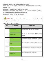
Page 40: ...te Step4 Press Enter to set up the value 6 2 5 9 Special Function Setup No LCD Display Explanation 1 To set up the constant PV voltage 2 To set up the multiple MPPTs parallel mode 3 To enable the High...

Page 41: ...15 To enable the PU curve 16 To enable the shadow MPPT mode 6 2 5 9 1 Island Protection The active anti islanding protection of the inverters is achieved by shifting the frequency of the inverter away...

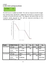
Page 42: ...port The diagram and table below are the response mode required for the volt var response according to the standard of AS NZS 4777 2 2020 Region Default Value VV1 VV2 VV3 VV4 Australia A Voltage 207...

Page 43: ...ep2 go to Special Func and then go to QU Curve Step3 enable or disable the Volt var Response Mode by changing the status to ON or OFF 6 2 5 9 3 Volt watt Response Mode The PU Curve is enabled by defau...

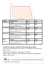
Page 44: ...vel P of Srated 100 20 New Zealand Voltage 242 V 250 V Inverter maximum active power output level P of Srated 100 20 Procedures to enable or disable the Volt watt Response Mode Step1 go to All Set Ena...

Page 45: ...Q Curve and enable the Q Curve by change the status to ON Step3 go to Power Control and then go to Q Set Step 4 Set up the Reactive Power Mode manually Procedures to set up the Fixed Power Factor Mode...

Page 46: ...e restored with this function The total energy generated can be adjusted here 6 2 5 13 Reset Total E The total energy generated record can be cleared here and after clearing the energy generation reco...

Page 47: ...he inverter will stop working Under the detection mode menu you can choose CT mode or meter mode For the normal working of inverters please use the soft limit only The hard limit is used only by compu...

Page 48: ...t up by the installer following the step in Technical set on P32 6 2 5 6 2 5 16 Battery Set No LCD Display Explanation 1 To set up the BMS Agreement 2 To set up the max charge current 3 To set up the...

Page 49: ...ator to charge 12 The signal of the generator 13 The connection of generator compulsorily 14 The lowest value that the battery restarts 6 2 5 17 Safety Info No LCD Display Detail 1 SAFETY INFOR cAUSAS...

Page 50: ...e 50 0 Hz Time 5ms Enable ON Value 49 5 Hz Time 5ms Enable OFF Value 260V Time 5ms Enable ON Value 255V Time 5ms Enable ON Value 248V Time 5ms Enable ON Value 210V Time 5ms Enable ON Value 210V Time 5...

Page 51: ...ble ON Value 215V Time 5ms POINT1 U 253 Power 100 POINT1 U 150 Q 44 PF FIX VALUE 90 Q FIX VALUE 10 P FIX VALUE 100 7 Maintenance and Troubleshooting 7 1 General Maintenance PF FIX VALUE Q FIX VALUE P...

Page 52: ...he inverters will not be installed in a short term please store them in a dry room with the ambient temperature between 25 60 For storage and transportation please pack them in the original package if...

Page 53: ...s decrease solar panel quantity in series 5 Bus Over Voltage Hard Transient bus voltage exceeds the hardware protection limit 1 Check if the input voltage exceeds the inverter s upper limit of input v...

Page 54: ...h temperature inside inverters 1 Check the ventilation of installation environment 2 Avoid direct sunlight 12 Extern Flash Abnormality in external flash reading and writing Restart the inverter 13 Bus...

Page 55: ...eakage is out of range Check the AC connection and DC connection and check internal wire connection 20 DCI Out Range DC component is too large Restart the inverter or contact the installer 21 ISO Out...

Page 56: ...if the input voltage exceeds the inverter s upper limit of input voltage 2 Decrease solar panel quantity in series 26 Grid Volt Over 110 The grid is overloaded by 10 for over 10 minute 1 Wait for the...

Page 57: ...n the software limit and set up a software limit that is lower than the hardware limit 2 Turn off the hardware limit if permitted 32 PEN No Connect Grounding fault as the PE and N line has not been co...

Page 58: ...oltage is too low 1 Increase the battery quantity in series 2 Contact the installer 39 Battery Curr Hard High The hardware current of battery is too high 1 Decrease the battery quantity in parallel 2...

Page 59: ...57 battery 3 Contact the installer NOTE If any event in the above table is displayed please turn off the inverter wait 5 minutes and then restart the inverter...

Page 60: ...58 8 Specification...

Reviews: