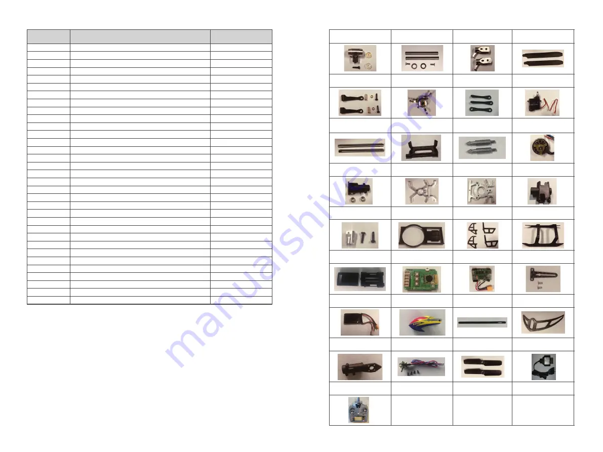
Illustrated Parts
List
Spare Parts
List
Notice for beginners:
1.
Please fly with an instructor until you are confident enough
.
2.
Before flying the model for the first time, you need to fully underst
an
d all of
the functions provided by the transmitter and the responses of all of the
switches.
3.
Do
n
o
t attempt to fly in 3D mode yet. Practice
hovering and flying
in 6G mode
until you are familiar with it. Then you can practice
hovering and
flying
in
3D
mode. Once you are familiar with these two modes you can
progress to
practicing inverted flight with an instructor.
4.
Practic
ing inverted
hovering
and inverted
flight
will
build a
solid
foundation
t
owards
achieving proficien
cy in
3D
flying.
5.
This model is not a toy and it can cause damage to people and property. I
t
is
recommended that you practice with a simulator on a computer before doing
real 3D fly
ing
with this model to minimize damage.
NO. PAR
T
NAME
QUANTITY
1
2
3
4
5
6
7
8
9
10
11
12
13
14
15
16
17
18
19
20
21
22
23
24
25
26
27
28
29
30
31
32
33
1
2
2
2
2
1
3
1
2
1
2
1
1
1
1
1
1
1
4
1
1
1
1
1
1
1
1
1
1
1
2
1
1
Main Rotor Head
Main Grip
Feathering
Shaft Set
Main Blade Grip Set
Main Blade Set
Primary Linkage Set
Swashplate
Secondary Linkage Set
Servo
Main Shaft
Set
Servo Mounting Plate
Canopy Mounting Post
s
Main Motor
Main Shaft Bearing Mount
Metal Frame Plate A
Metal Frame Plate B
Tail Boom
Mount
Main Shaft to Motor
Connect
o
r
Landing frame Set
Carbon Fiber Side Frame Set
Landing Skid Set
Flight Control Unit
B
ox
Integrated Flight Control Board
Power Distribution Board (PDB)
Anti Rotation Bracket
Battery
Canopy
Tail Boom
Tail Fin Set
Tail Motor Mount
Tail Motor
Tail Rotor
USB Charger
Radio Control
Part No: 2.32.01.E150-001
Part Name: Main Rotor Head
Part No: 2.32.01.E150-003
Part Name: Main Blade Grip Set
Part No: 2.32.01.E150-004
Part Name: Main Blade Set
Part No: 2.32.01.E150-006
Part Name: Swashplate
Part No: 2.32.01.E150-008
Part Name: Servo
Part No: 2.32.01.E150-009
Part Name:
Main Shaft
Set
Part No: 2.32.01.E150-010 Part
Name: Servo Mounting Plate
Part No: 2.32.01.E150-012
Part Name: Main Motor
Part No: 2.32.01.E150-014 Part
Name: Metal Frame Plate A
Parit No: 2.32.01.E150-015 Part
Name: Metal Frame Plate B
Part No: 2.32.01.E150-016
Part Name: Tail Boom
Mount
Part No: 2.32.01.E150-017
Part Name:
Main Shaft to
Motor Connector
Part No: 2.32.01.E150-002
Part Name: Main Grip
Feathering
Shaft Set
Part No: 2.32.01.E150-005
Part Name: Primary Linkage
Set
Part No: 2.32.01.E150-007
Part Name: Secondary Linkage
Set
Part No: 2.32.01.E150-011
Part Name: Canopy
Mounting Post
s
Part No: 2.32.01.E150-013 Part
Name: Main Shaft Bearing
Mount
Part No: 2.32.01.E150-018 Part
Name
:
Landing frame Set
Part No: 2.32.01.E150-019
Part Name: Carbon Fiber
Side Frame Set
Part No: 2.32.01.E150-020
Part Name: Landing Skid Set
Part No: 2.32.01.E150-21
Part Name: Flight Control Unit
B
ox
Part No: 2.32.01.E150-22
Part Name: Integrated Flight
Control Board
Part No: 2.32.01.E150-23 Part
Name: Power Distribution
Board (PDB)
Part No: 2.32.01.E150-24
Part Name:
Anti
R
otation
B
racket
Part No: 2.32.01.E150-25
Part Name
:
Battery
Part No: 2.32.01.E150-26
Part Name:: Canopy
Part: No: 2.32.01.E150-27
Part Name: Tail Boom
Part No: 2.32.01.E150-28
Part Name: Tail Fin Set
Part No: 2.32.01.E150-29
Part Name
:
Tail Motor Mount
Part No: 2.32.01.E150-30
Part Name: Tail Motor
Part No: 2.32.01.E150-31
Part Name: Tail Rotor
Part No: 1.03.04.001
Part Name
:
USB Charger
Part No: 2.03.01.T6-001
Part Name: Transmitter
-12-
-11-
Summary of Contents for E150
Page 1: ...User Manual E150...


