Black GND
Red +5V Input
Green smare Audio
Yellow Video_IN
8 7 6 5 4 3 2 1
, , , , , , ,
Band LED
Channel LED
400MW
200MW
25MW
U FL
.
Cam IN
_
+
5V out put
GND
Switch Button
Blue Video out
_
1 2 3 4 5
, , , ,
Frequency and channel frequency table
:
CH
FR
BandA(1)
BandB(2)
BandE(3)
BandF(4)
BandR(5)
C 1
H
5865M
5733M
5705M
5740M
5658M
C 2
H
5845M
5752M
5685M
5760M
5695M
C 3
H
5825M
5771M
5665M
5780M
5732M
C 4
H
5805M
5790M
5665M
5800M
5769M
C 5
H
5785M
5809M
5885M
5820M
5806M
C 6
H
5765M
5828M
5905M
5840M
5843M
C 7
H
5745M
5847M
5905M
5860M
5880M
C 8
H
5725M
5866M
5905M
5880M
5917M
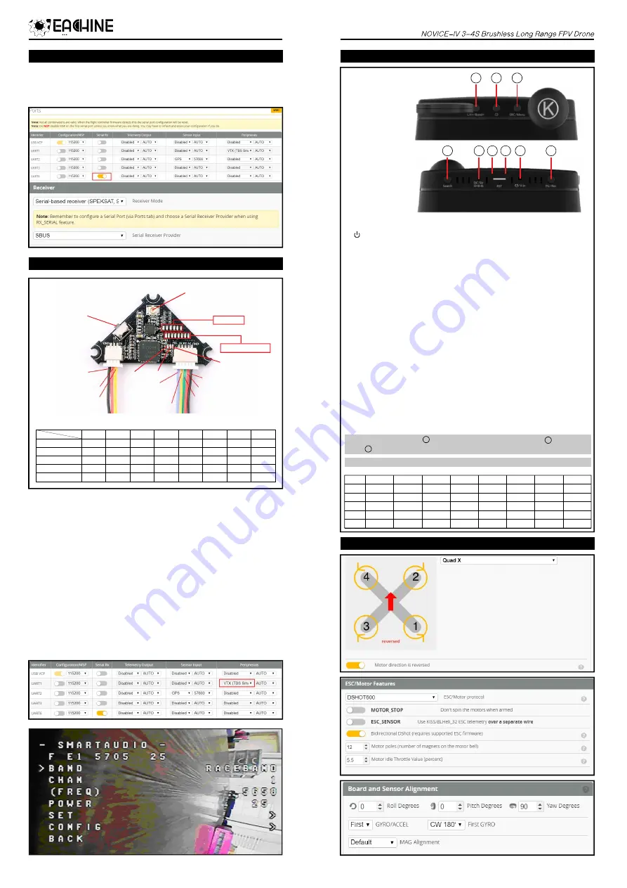
9.Receiver configuration
There are 3 ways to switch the vtx channels:
Short press the
to choose the VTX channel, press and holding
1.
the button to hoose the VTX Band (Can't save , it will lost the channel while power off)
C
2. Go to Betaflight CLI ,type the command:
Set vtx_band=3
Set vtx_channel=1
save
Notes: The vtx_freq should match the vtx_band and vtx_channle as the VTX Channel
list shows.
For example, if you set vtx_freq=5732, you should set vtx_band=5 and
VTX_channel=3
Enable Smartaudio for UART1, then move the stick of the transmitter (THR MID+
3.
YAW LEFT+ PITCH UP) to enter OSD Menu, Enter to Features, then enter to VTX SA
to set VTX Band and channel
switch button
10.VTX Bands and Channels setup
11.Goggles and VTX Receiver channel setting
12.Mixer type,ESC/MOTOR protocol and Sensor alignment
Please enable Serial RX for UART6 from port tab, then set Receiver mode to be
Serial-based receiver from the Configuration tab of the Betaflight Configurator,
then select SBUS protocol for the Serial Receiver Provider.
Buttons and ports
4
5 6 7
8
9
1)CH+/Bamd+
Short press this button select CH 1-8 cycles
2) POWER and RETURN
Long press to boot/shut down.
short press during working as return
3)SRC/MENU
Short press to select from video sources V-in/RF A/RF B/Diversity
Long press to call out MENU
4)SEARCH
Press to automatically search for the signals;
5)CHARGING PORT
DC 5-18V wide range recharging port/power backup port,typically@5V/2A;
6)RESET
Reset hole.Shut down device when necessary;
7)TF CARD SLOT
Support up to 32G,typical@C10;
8)VIDEO IN/AUDIO OUT PORT
Video input@AV in mode;Audio output@RF mode;
9)Pic/Rec
Short press to take a screen shoot and save picture
Long Press to start recording a video,then a short press to save video.
Charging indicator LED:charging-red;full charged-green.
In MENU operatins,press to shift down to select settings;press as+settings;
press as-settings.
3
4
1
Band
A
B
E
F
R
C 2
H
5845
5752
5685
5760
5695
C 3
H
5825
5771
5665
5780
5732
C 4
H
5805
5790
5645
5800
5769
C 5
H
5785
5809
5885
5820
5806
C 6
H
5765
5828
5905
5840
5843
C 7
H
5745
5847
5925
5860
5880
C 8
H
5725
5866
5945
5880
5917
C 1
H
5865
5733
5705
5740
5658
1
2
3
Fix the CCW propeller onto the M1
and M4 motor (CCW motors)
Fix the CW propellers onto the M2
and M3 motor (CW motors)
Prop Out


