background image

KO-II

MANUAL

4

www.

eaeelectric

.com

www.

eaeelectric

.com

General

N

N

BUSBARS SHOULD 

NOT BE IN TOUCH WITH 

ANY LIQUID MATERIAL 

Dry 

Envoirement

Rain

Drops

Please use canopy

for outdoor 

applications. 

Please use porch

for outdoor.

Please use porch

for outdoor.

 Please use canopy

for building expension 

points. 

Chemicals

Urine

Water

CLOSE 

INDIRECT or DIRECT 

WATERWAYS

 BUSBARS THAT ARE NOT 

ASSEMBLED COMPLETELY 

HAVE NO PROTECTION

AGAINST TO WATER

Summary of Contents for E-Lineko-II

Page 1: ...E LINEKO II MANUAL www eaeelectric com ...

Page 2: ...E LINEKO II ...

Page 3: ...pecial Lengths Offset Sizing Busbar Mounting Instructions For Joints Fire Barriers Points To Be Taken Into Consideration After Installation KOP 40 80 Tap Off Boxes KOP 160 250 400 Tap Off Boxes Feed Box Installation B10 B11 Energizing Before Energizing Energizing The Equipment Maintenance 2 3 4 5 6 7 8 9 10 11 12 13 14 15 16 17 18 19 20 21 ...

Page 4: ...read carefully and acted upon before taking delivery of equipment on site Handling installation and operation of busbar systems should be carried out only by skilled trained and authorized personnel using all associated equipment such as rubber gloves helmet safety glasses or face shields and flash resistant clothing in accordance with established safety practices Please do not handle the equipmen...

Page 5: ... to test energize clean ground label and lock the system and equipment suitable for occupational safety applications Be trained in the use and maintenance of personal protective equipment such as rubber gloves helmets protective goggles or face shields and gauze resistant clothing in accordance with relevant work safety practices and potential hazard levels Must be trained in first aid WARNING Dan...

Page 6: ... Envoirement Rain Drops Please use canopy for outdoor applications Please use porch for outdoor Please use porch for outdoor Please use canopy for building expension points Chemicals Urine Water CLOSE INDIRECT or DIRECT WATERWAYS BUSBARS THAT ARE NOT ASSEMBLED COMPLETELY HAVE NO PROTECTION AGAINST TO WATER ...

Page 7: ...d be checked by unpacking them sufficiently to inspect them for possible transit damage and to determine that the shipment is complete and correct as per Packing List provided If any of the items is missing from the Packing List or any piece is damaged during transportation Insurance Company must be informed immediately for proper reporting with all required documents for further action 4 All busb...

Page 8: ...conditions permit do not disassemble the busbar until it reaches the lastest installation point 8 Storage area should be a clean dry space with a uniform temperature to prevent condensation and having adequate air circulation and protected from dirt fumes water Storage area should be free of vehicle traffic to prevent physical damage to the products 9 When busbar straight lengths and modules are t...

Page 9: ...ould be used in earthquake risk areas Please contact our company for details of seismic support products and project planning The recommended distance between supports is 1 5m the maximum distance is 2m Make sure that support positions do not block either joint covers or tap off points 4 DDT modules should be used at min 20cm distance to the each floor concrate 5 If the busbar lines are used in th...

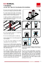
Page 10: ...inished roofs and walls during installation Min From 4 points 9 Tools required for the installation Micrometer type adjustable calibrated torque spanner inch square drive size 10mm 13mm and 19mm socket Drilling Machine Size 10mm Spanner Socket Screwdriver Hoist with cloth sling 10 The busbar to be installed needs to be hanged min 4 points as shown in below picture Points to be taken into considera...

Page 11: ...detailed on the project drawings All modules have a block joint end and the other end of the module has not block joint See as shown Figure 1 1 1st Busbar 2 2nd Busbar 3 Block Joint 3 1 Locker Piece 3 2 Insulators 3 3 Double Headed Nut 3 4 Plastic Seperator Piece 4 Conductors 5 Front Cover Plate 6 Top Cover Plate 7 Joint Protection Plate 8 Bottom Cover Plate Figure 1 Figure 2 a b ...

Page 12: ...ll be manufactured as per X value 3 In the case in where custom made intermediate size busbars are required both ends of the intermediate size busbars can be produced with or without block joints In such cases please contact our company for technical support and technical information Note Please send a drawing for combined offsets when ordering Indicate bolted and non bolted ends on the drawing A ...

Page 13: ...or 2 Introduce bolted and non bolted ends of the busbar into each other carefully until the cover plate screws can be put in Figure 3 4 Tighten the double headed nut untill upper nut is broken 6 Install top and bottom joint cover plates Check the joint before fitting the last joint side cover plate Fit the joint cover side plate and tighten the screws Check the position of the earth conductor when...

Page 14: ...ulation plates of the joint are not cracked or broken 8 If removal is required for any reason tighten the nut using a calibrated torque wrench adjusted to 55 Nm 40 lbft after re fitting the block joint set 7 1 1 2 3 4 3 1 2 3 4 5 1 2 3 4 2 4 6 55 Nm 40lbft 8 Busbar Mounting Instructions For Joints ...

Page 15: ...e Barrier Fire Barriers Dimensioning of Fire Barrier When placing an order for fire barriers to be installed in the KO II busbar the following information is required 1 Thickness of floor or wall in cm A mm 2 Centreline dimension of the fire barrier should be measured from the side without the block joint Y mm 3 There will be no plug in points at the fire barrier location 4 EAE Supplies a 300 mm t...

Page 16: ...er the busbar system is energized loads must be switched in sequence main and sub feed 2 4 When the busbar is used properly it will have a moderate hum Excessive noise may be an indication of hardware that has not been extruded or incorrectly mounted metal parts 2 5 Spark formation at any point along the busbar is not normal The busbar must be de energized and de energized until the spark conditio...

Page 17: ... applications Please do not drill the busbar at any place where is marked with red on the picture 13 Take precautions against adverse environmental conditions such as rain and snow In addition the busbar dripping cement etc inside the building Protect from water malfunctioning piping and all fluids that may come from water jets Cover if necessary Cap the ends to the busbar joint points that have n...

Page 18: ... in parallel to the busbar check the position of the earth contact 4 When the box is secured to the busbar housing closed the box cover and tighten the screws 1 3 2 4 Important When the cover is the closed due to interlock security mechanisms tap off box can not be installed or removed from the busbar Attention Check the box once more before making connections KOP 40 80 Tap Off Boxes ...

Page 19: ...d bolt to loosen mechanical fixing clamps Push left side of tap off box towards busbar and lock fixing clamps to the busbar Tight back the plastic headed bolt to hold busbar rigidly 4 Tight the plastic headed bolt on the right side to fix the tap off box mechanicaly to the busbar 1 3 2 4 Important When the cover is the closed due to interlock security mechanisms tap off box can not be installed or...

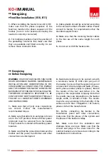
Page 20: ...t all joint zone connections are correct Follow the manufacturer s recommended torque 2 Make sure that all bolt on and plug in boxes are in the off position Boxes without power interrupts must be removed from the busbar if they cannot be isolated with auxiliary power breakers 3 Make sure that the connections between the busbar and the panel transformer and other connections are interrupted 4 Resis...

Page 21: ...7 All busbar ratings routings and supporting systems should be checked as per final isometric drawings 7 All busbar ratings routings and supporting systems should be checked as per final isometric drawings 8 All busbar system should be checked visually to be certain that they are clean and secure Loose and or contaminated connections increase electrical resistance which can cause overheating 9 Any...

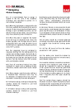
Page 22: ...ld be checked 4 The connected equipment should be energized in sequence by starting at the source to end of the system 5 After all overcurrent devices have been turned on loads such as lighting circuits contactors heaters and motors may be turned ON 6 EAE busbar system is particularly quiet when operating normally In some installations however there may be a moderate hum Excessive noise may be an ...

Page 23: ...ices Important Hazardous voltages in electrical equipment can cause severe personel injury or death unless otherwise specified Installation inspection and preventive maintenance should only be performed on busbar system to which power been turned off disconnected and electrically isolated so that no accidential contact can be made with energized parts Operation of busbar trunking which has been wa...

Page 24: ...www eaeelectric com 22 KO IIMANUAL ...

Page 25: ...MIRATES SUDAN TANZANIA CHILE VIETNAM TURKMENISTAN MADAGASKAR SPAIN U A EMIRATES CAMEROON THAILAND CHILE TURKMENISTAN KUWAIT SYRIA ETHIOPIA MADAGASKAR TANZANIA FRANCE CAMEROON SYRIA U A EMIRATES KENYA LUXEMBOURG FRANCE UZBEKISTAN PERU CHILE SUDAN OMAN IRAQ MADAGASKAR LATVIA QATAR THAILAND TURKEY TURKEY TURKEY TURKEY TURKMENISTAN MACEDONIA IRELAND VIETNAM GHANA CZECH REP GREECE SPAIN U KINGDOM CROAT...

Page 26: ...fice Akcaburgaz Mahallesi 3114 Sokak No 10 34522 Esenyurt Istanbul TURKEY Tel 90 212 866 20 00 Fax 90 212 886 24 20 EAE DL 3 Factory Busbar Makine Ihtisas Organize Sanayi Bolgesi Mahallesi 6 Cadde 8 Sokak No 6 41455 Dilovası Kocaeli TURKEY Tel 90 262 502 05 65 Fax 90 262 502 05 70 IEC 61439 6 T E s E 344805 9001 14001 18001 27001 ISO İ R E L M E T S İ S M İ T E N Ö Y ...

Reviews: