Installation, Operation and Parts Manual
EE-6501
18
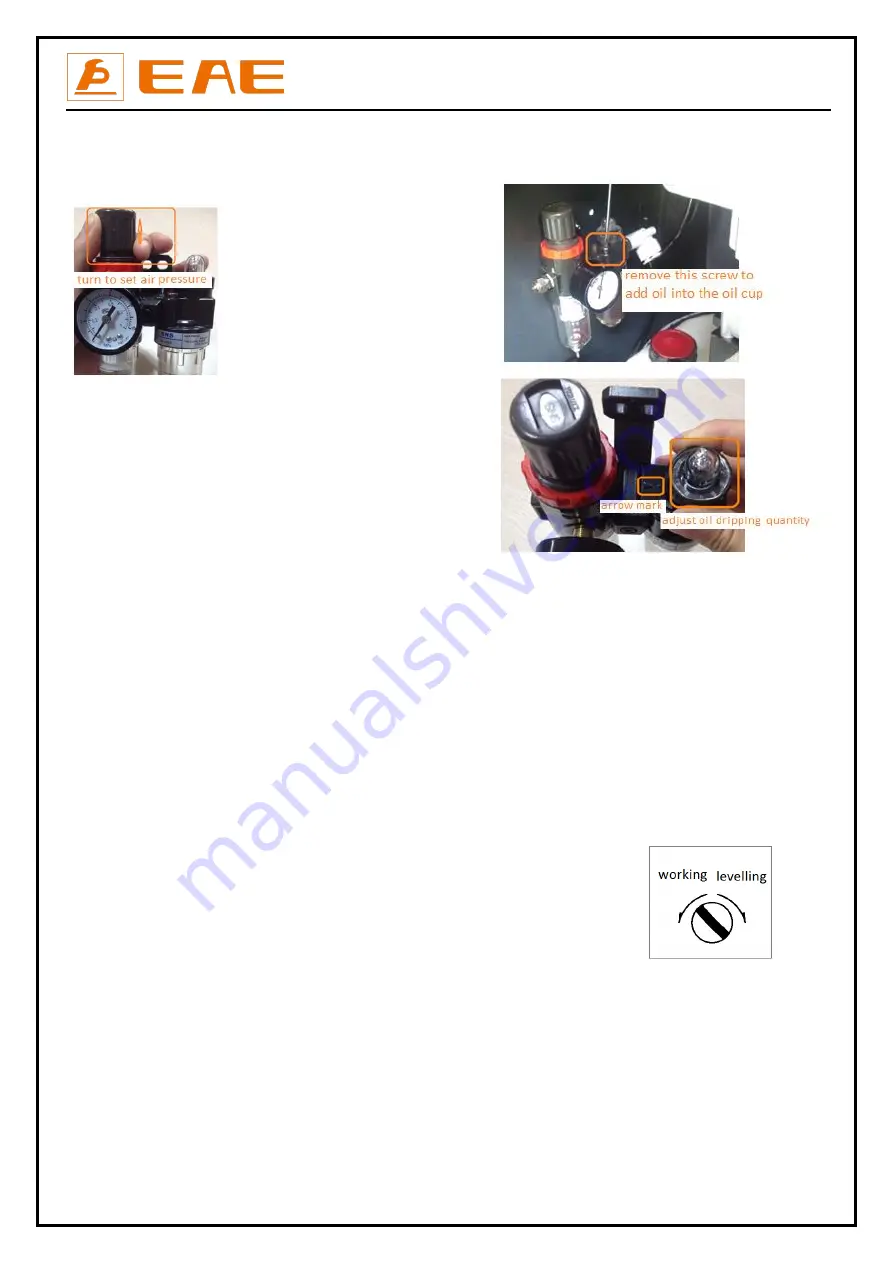
Set the pneumatic pressure between 6-8 bars.
Push upward the button indicated in the following fig and turn the button until the hand of the pressure meter points to the NUMBER ”6” .
Push the button down thereafter.
It is suggested to add ISO VG32 mechanical oil into the oil tank.
Adjust the oil dipping quantity using the button on top of the oil cup.
Step 7: Fill with hydraulic oil.
CLEAN AND FRESH OIL ONLY. DON’T FILL THE TANK COMPLETELY FULL.
Lift must be fully lowered before changing or adding hydraulic oil.
Pour 10 liters of anti-abrasion hydraulic oil into the oil tank. The level of oil shall reach the tippets volume mark of the tank.
Add more oil after running the lift for several cycles until the lift can rise to the maximum lifting height.
Note
:
It is suggested to use HM NO.46 hydraulic oil .Use HM NO.32 hydraulic oil when temperature is below 10 degree Celsius.
Change the oil 6 months after initial use and change once per year thereafter.
Step 8: Levelling
Refer to 5.2 and 5.4 operation instructions and turn SA2 to “OFF” mode before levelling operation.
Check the connection of the hydraulic and electrical system before levelling operation. Ensure the oil hoses are correctly connected.
Otherwise, oil cylinders may not work synchronously or could be damaged.
Review operation instructions and get familiar with lift controls by running the lift through a few cycles before levelling o peration. In
addition, operators need to know clear which levelling valve controls which platform. This could be judged by the way that the oil hose
was connected or by trial raising or lowering.
1. When open the door of the control unit you could see a switch that can shift
the lift from normal working mode to levelling mode or vise versa.
Firstly, the operator should turn the switch to levelling mode
and judge which platform is controlled by DOWN I and which by DOWN II
by trial raising and lowering.
And then push DOWN I and DOWN II at the same time to have both platforms raised to the highest position.
2. Push the UP button to lower both platforms to the lowest position. Repeat this step for several times to vent the air remained in the oil
hose.
3. Turn the switch to the normal working mode and push the UP button to check if both platforms are working synchronously. If they are,
operator can carry out trial running.
4. In case both platforms do not run synchronously, turn the switch to the working mode and push DOWN I and DOWN II to lower both
platforms to the lowest position. (If being equipped with an alarming buzzer, alarming buzz can be heard when you push DOWN II button to
lower the platform)
Summary of Contents for EE-6501
Page 10: ...Installation Operation and Parts Manual EE 6501 10 3 3 Dimensions...
Page 14: ...Installation Operation and Parts Manual EE 6501 14 Recessed mounting...
Page 27: ...Installation Operation and Parts Manual EE 6501 27 Annex 1 Wiring diagrams and parts list...
Page 28: ...Installation Operation and Parts Manual EE 6501 28...
Page 37: ...Installation Operation and Parts Manual EE 6501 37...


