Installation, Operation and Parts Manual
EE-6501V2
17
Step
7:
Fill
with
hydraulic
oil.
CLEAN
AND
FRESH
OIL
ONLY.
DON’T
FILL
THE
TANK
COMPLETELY
FULL.
Lift
must
be
fully
lowered
before
changing
or
adding
hydraulic
oil
Pour
18
liters
HM32
anti
‐
abrasion
hydraulic
oil
into
the
oil
tank.
The
level
of
oil
shall
reach
the
tippets
volume
mark
of
the
tank.
Add
more
oil
after
running
the
lift
for
several
cycles
until
the
lift
can
rise
to
the
maximum
lifting
height.
Note
:
As
running
speed
of
the
lift
is
mainly
decided
by
the
viscosity
of
the
hydraulic
oil,
we
suggest
using
NO.46
hydraulic
oil
when
average
temperature
of
the
location
is
above
18
degree
Celsius
and
using
NO.32
hydraulic
oil
when
temperature
is
below
18
degree
Celsius.
Change
the
oil
6
month
after
initial
use
and
change
once
per
year
thereafter.
Step
8:
Leveling
Refer
to
5.4
operation
instructions
and
turn
off
the
infrared
switch
before
leveling
operation
Attention:
Level
the
platforms
before
connecting
height
limit
switch
because
if
not,
platforms
cannot
rise
to
the
highest
position.
Before
leveling,
make
sure
the
oil
hoses
are
correctly
connected.
Otherwise,
oil
cylinders
may
not
work
synchronously
or
could
be
damaged.
In
addition,
operators
need
to
know
clear
which
leveling
valve
controls
which
platform.
This
could
be
judged
by
the
way
that
the
oil
hose
was
connected
or
by
trial
raising
or
lowering.
Manual
leveling
Open
one
of
the
leveling
valves
and
press
the
UP
button
to
supplement
oil
to
the
oil
hose
connected.
Close
the
valve
to
stop
adding
oil.
In
normal
working
condition,
both
leveling
valves
are
closed.
If
both
valves
are
open,
two
platforms
of
the
lift
can
still
rise
but
will
not
move
upwards
synchronously.
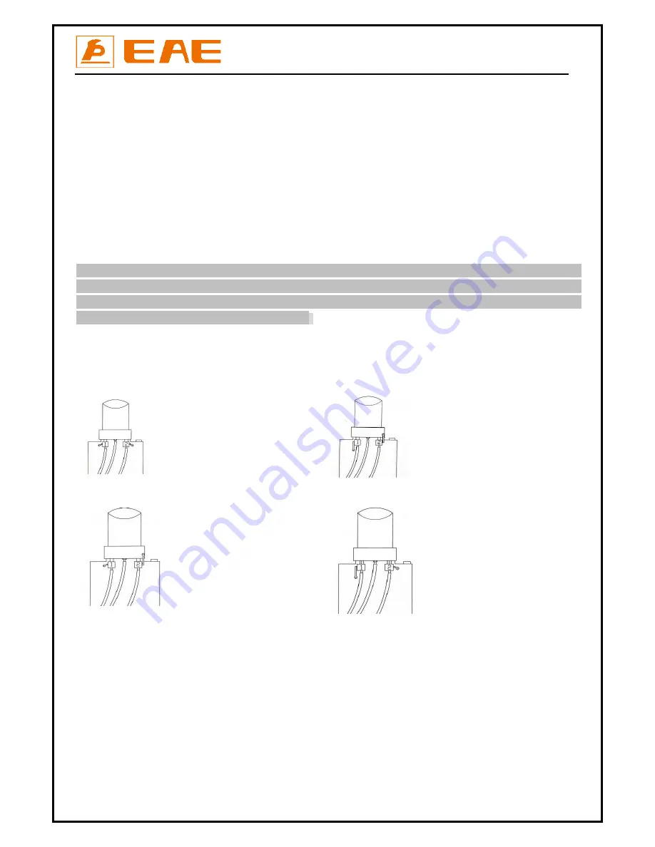
A.
Both
valves
open
B.
Both
valves
closed
:
Normal
working
C.
D.
One
valve
open,
the
other
closed:
leveling
condition
A.1.
Open
both
leveling
valves
and
press
the
UP
button
to
have
both
platforms
raised
to
the
highest
positions.
Repeat
this
step
for
two
or
three
times.
(Take
care
that
this
step
could
be
time
consuming,
because
there’s
air
in
the
cylinders
and
no
load
on
the
platforms.)
A.2.
Close
both
leveling
valves
as
per
drawing
B.
Press
the
UP
button
to
see
if
both
platforms
rise
synchronously.
(Normally,
till
now
the
platforms
may
not
rise
synchronously.)
A.3.
If
not
work
synchronously,
one
platform
may
rise
faster
than
the
other.
Users
should
first
judge
which
leveling
valve
controls
which
platform
and
then
open
the
valve
that
controls
the
slower
‐
rising
platform
to
supplement
oil
into
its
oil
hose.
Press
the
UP
button
to
make
both
platforms
rise
to
the
same
height.
(The
other
valve
here
must
be
closed.)
A.4.
Close
both
leveling
valves.
Press
DOWN
I
button
to
have
both
platforms
lowered
to
the
lowest
position.
Summary of Contents for EE-6501V2
Page 10: ...Installation Operation and Parts Manual EE 6501V2 10 3 3 Dimensions Unit mm...
Page 27: ...Installation Operation and Parts Manual EE 6501V2 27 Annex1 Wiring diagrams and parts list...
Page 28: ...Installation Operation and Parts Manual EE 6501V2 28...
Page 29: ...Installation Operation and Parts Manual EE 6501V2 29...
Page 33: ...Installation Operation and Parts Manual EE 6501V2 33...
Page 37: ...Installation Operation and Parts Manual EE 6501V2 37...


