Installation, Operation and Parts Manual
EE-6501V2
31
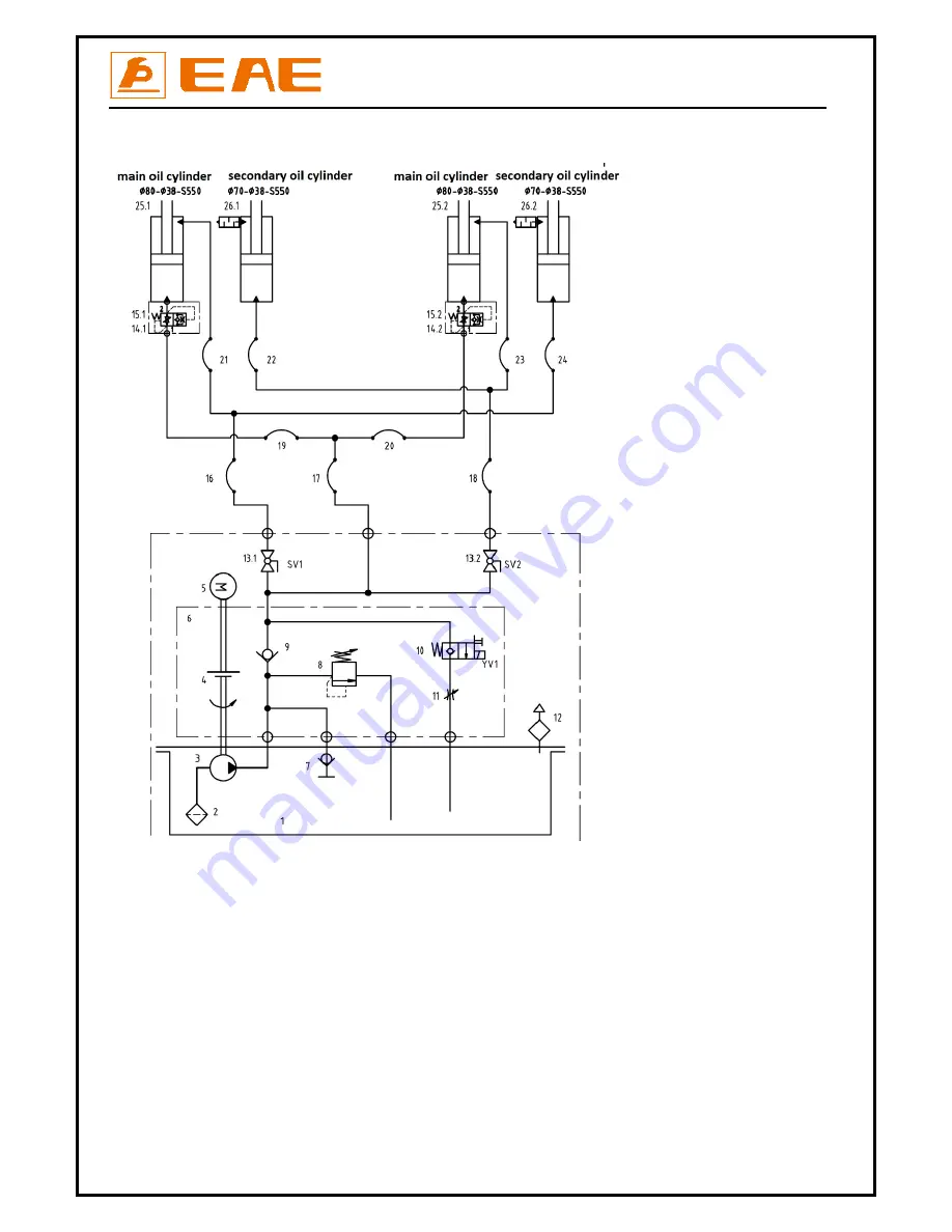
Annex2,
Hydraulic
diagrams
and
parts
list
1.
Oil
tank
2.
Filter
3.
Gear
pump
4.
Coupling
5.
Motor
6.
Hydraulic
block
7.
Cushion
valve
8.
Overflow
valve
9.
Single
way
valve
10.
Solenoid
unloading
valve
11.
Throttle
valve
12.
Tank
cover
13.
Leveling
ball
valve
14.Connector
of
parachute
valve
(
optional
)
15.Parachute
valve
(
optional
)
16
‐
24.
oil
hose
25.
Main
oil
cylinder
26.
The
secondary
oil
cylinder
Summary of Contents for EE-6501V2
Page 10: ...Installation Operation and Parts Manual EE 6501V2 10 3 3 Dimensions Unit mm...
Page 27: ...Installation Operation and Parts Manual EE 6501V2 27 Annex1 Wiring diagrams and parts list...
Page 28: ...Installation Operation and Parts Manual EE 6501V2 28...
Page 29: ...Installation Operation and Parts Manual EE 6501V2 29...
Page 33: ...Installation Operation and Parts Manual EE 6501V2 33...
Page 37: ...Installation Operation and Parts Manual EE 6501V2 37...


