2. Install cam roller assemblies onto the brake shoes.
3. Install the camshaft into the spider. Install spacer wash-
er and lock ring on cam before sliding the cam thro u g h
the camshaft support bracket. Install the slack adjuster
and the lock ring.
10
N OTE T
O E N S U R E B RA K E S M E E T
F. M . V.S.S. 121
P E R
-
FO R M A N C E R E QU I R E M E N T S
, S
P I C E R
T
RA I L E R
P
RO D U C T S R E C O M
-
M E N D S T H AT O N LY O R I G I N A L E QU I P M E N T B RA K E C O M P O N E N T S B E
U S E D
.
WA R N I N G W
H E N R E A S S E M B L I N G B RA K E S
, S
P I C E R
T
RA I L E R
P
RO D U C T S R E C O M M E N D S T H AT T H E B RA K E R E T U R N
S P R I N G S B E R E P L AC E D W I T H N E W S P R I N G S TO A S S U R E P RO P E R
O P E RAT I O N O F T H E B RA K E
.
5. Remove brake re t u rn springs.
6. Remove camshaft lock ring, spacer washer, and cam
s h a f t .
7. Remove cam roller and shaft (in the case of the cast
shoe, remove roller shaft set screw and roller assembly)
and anchor pin bushing from shoes.
8. Remove anchor pin bushings, camshaft bushing and
seals from spider.
B RAKE ASSEMBLY
1. Install new anchor pin bushings, camshaft bushing
and camshaft seals into the spider.
WARNING W
H E N I N STA L L I N G C A M S H A F T S E A L S
,
T H E S E A L O N T H E S L AC K A D J U ST E R S I D E S H O U L D B E I N STA L L E D
W I T H S E A L FAC I N G I N TO S P I D E R
. T
H I S A L LOWS G R E A S E TO P U RG E
O U T S I D E T H E B RA K E A S S E M B LY W H E N G R E A S I N G T H E C A M S H A F T
BU S H I N G
. F
A I L U R E TO FO L LOW T H I SP RO C E D U R E C O U L D C AU S E
G R E A S E TO C O M E I N TO C O N TAC T W I T H B RA K E L I N I N G S
,
C AU S I N G
B RA K E FA I L U R E
.
4. Install the brake re t u rn springs on the brake shoes.
5. Position brake shoes on the spider and insert the
anchor pins.
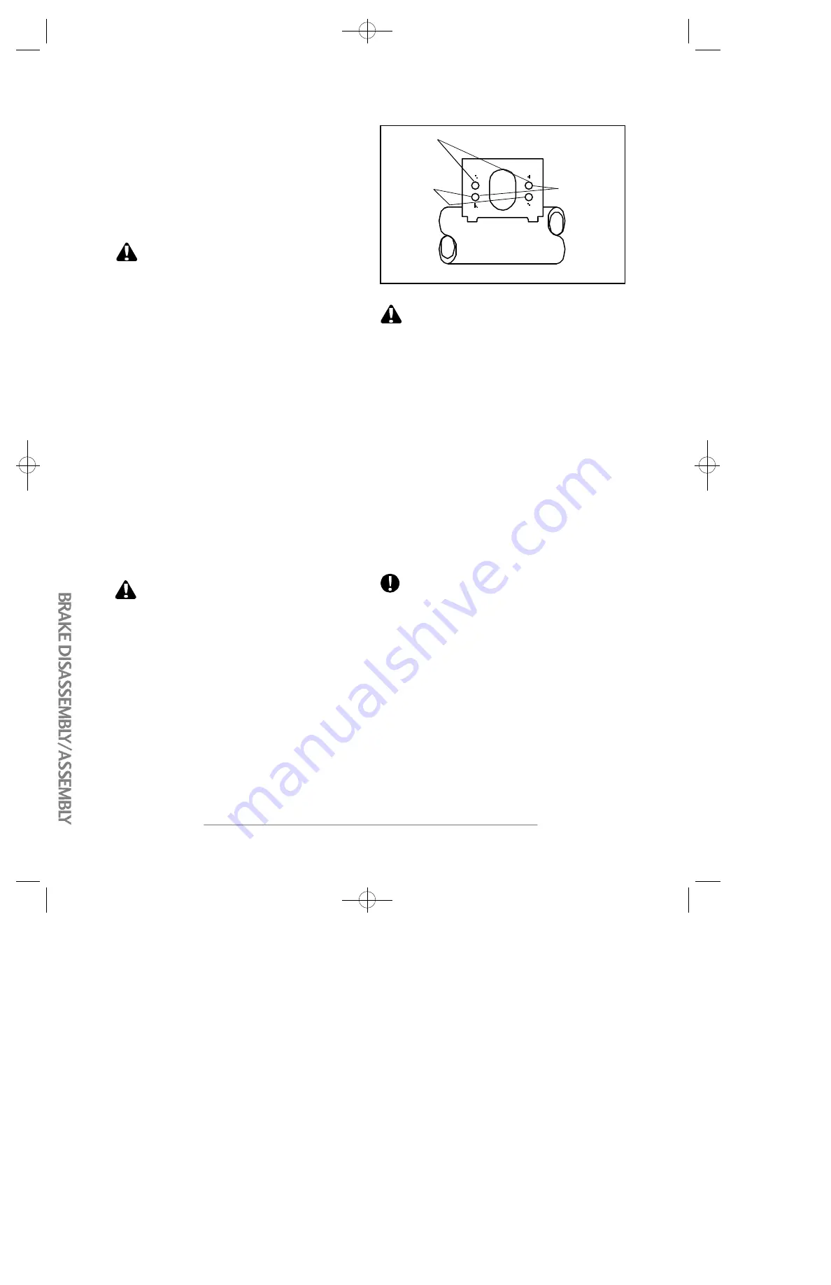
6. If air brake chambers are replaced, the correct mounting
holes must be used to correspond to brake adjuster length
(See Fig.4).
7. Connect slack adjuster to brake chamber push rod.
8. Adjust brakes as outlined in brake adjustment
p ro c e d u re s .
FIG. 4
6" B
RA K E
A
D J U ST E R
(A-A H
O L E S
)
5" B
RA K E
A
D J U ST E R
(B-B H
O L E S
)
5 1/2"
B
RA K E
A
D J U ST E R
(A-B H
O L E S
)
Any questions or comments on the above pro c e d u re should
be directed to the Spicer Trailer Engineering Depart m e n t .
B RAKE DISA S S E M B LY / A S S E M B LY
C AUTION E
XC E S S I V E P O U N D I N G O N A N C H O R P I N S
O R C A M RO L L E R P I N S TO R E M OV E O R I N STA L L T H E M C A N DA M AG E
T H E P I N SA N D C AU S E M I SA L I G N M E N T O F T H E B RA K E S P I D E RS A N D
B RA K E S H O E S
. T
H E U S E O F A S O F T H A M M E R O R B RA S S D R I F T
I S R E C O M M E N D E D TO R E M OV E O R I N STA L L T H E A N C H O R P I N S
I F N E C E S SA RY
.
B RAKE DISA S S E M B LY:
1. Release brakes and back off slack adjuster.
2. Remove slack adjuster lock ring and slack adjuster.
3. Remove brake dru m .
4. Remove anchor pins and brake shoes.
D22/P22 Manual pdf 9/23/97 2:48 PM Page 12
Summary of Contents for 20 Ton XPT
Page 6: ...Page 4...
Page 12: ...Page 10...
Page 17: ...Page 15...
Page 22: ...Page 20...
Page 23: ...Page 21...
Page 25: ...Page 23...
Page 26: ...Page 24...
Page 27: ...Page 25...
Page 28: ...Page 26...
Page 32: ...Page 30...
Page 34: ...Page 32...
Page 49: ......
Page 55: ......
Page 57: ......
Page 58: ......
Page 59: ...2017...


