4810 Clover Road • Greensboro, NC 27450 • 1-800-336-2776 • www.eagleequip.com • © Eagle Equipment 2018.01 • page 10
POSITION AND INSTALLATION
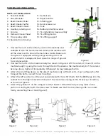
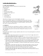
PARTS OF THE BALANCER
1. Rotation Pedal
2. Rise-fall Pedal
3. Bead Breaker Pedal
4. Bead breaker buffer
5. Bead Breaker shovel
6. Auxiliary rotating rod
7. Column
8. Demount/mount head
9. Tire pressing roller
10. Raise-fall control valve
1. Unscrew the nuts at the bottom, position the machine and
calibrate it with the horizontal rule. Mount the machine with
all the screws and to ensure the machine is stable. Make sure
the system is equipped with a good grounding circuit for
prevent electric leakage and have operation range of ground
for skid prevention.
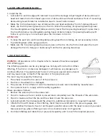
2. Unscrew the nut A on the machine body B as shown in Figure 4. Lift the column C; mount it on the
machine body B by using the nut A through the bolt located on the machine body B. If the column
becomes loose, tighten it immediately. Otherwise this may damage the tire.
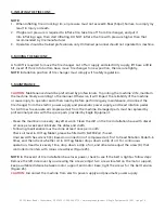
3. Attach the tire lifting device on the side of machine body with bolt set A, shown as Figure 5; after
fixing all the bolts, connect the air hose B&C.
4. Attach the left assist arm on the post and cabinet with 10pcs M10 bolts. Put the 8MM pipe into the
cabinet from the right reservation hole (2) of the machine and plug on the three-way connection,
as shown in Figure 6.
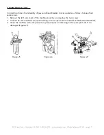
5. Attach the cylinder T1 on the swing arm with 2 bolts T2. Attach the tire pressing roller on the
piston rod and tighten with the hex screws T3. Make sure that the tire pressing roller can rotate
freely; connecting the air hose (Figure 7).
Figure 3
Figure 7
Figure 6
Figure 5
Figure 4
11. Vertical arm
12. Adjust handle
13. Inflating gun
14. Quick release nut
15. Cone
16. Rubber protection washer
17. Tire installation base assembly
18. Tire lifting device
19. Tire lifting support


