10
Eagle Eye Power Solutions, LLC | 877-805-3377 | www.eepowersolutions.com
Section 3. Installation & Cabling
(continued)
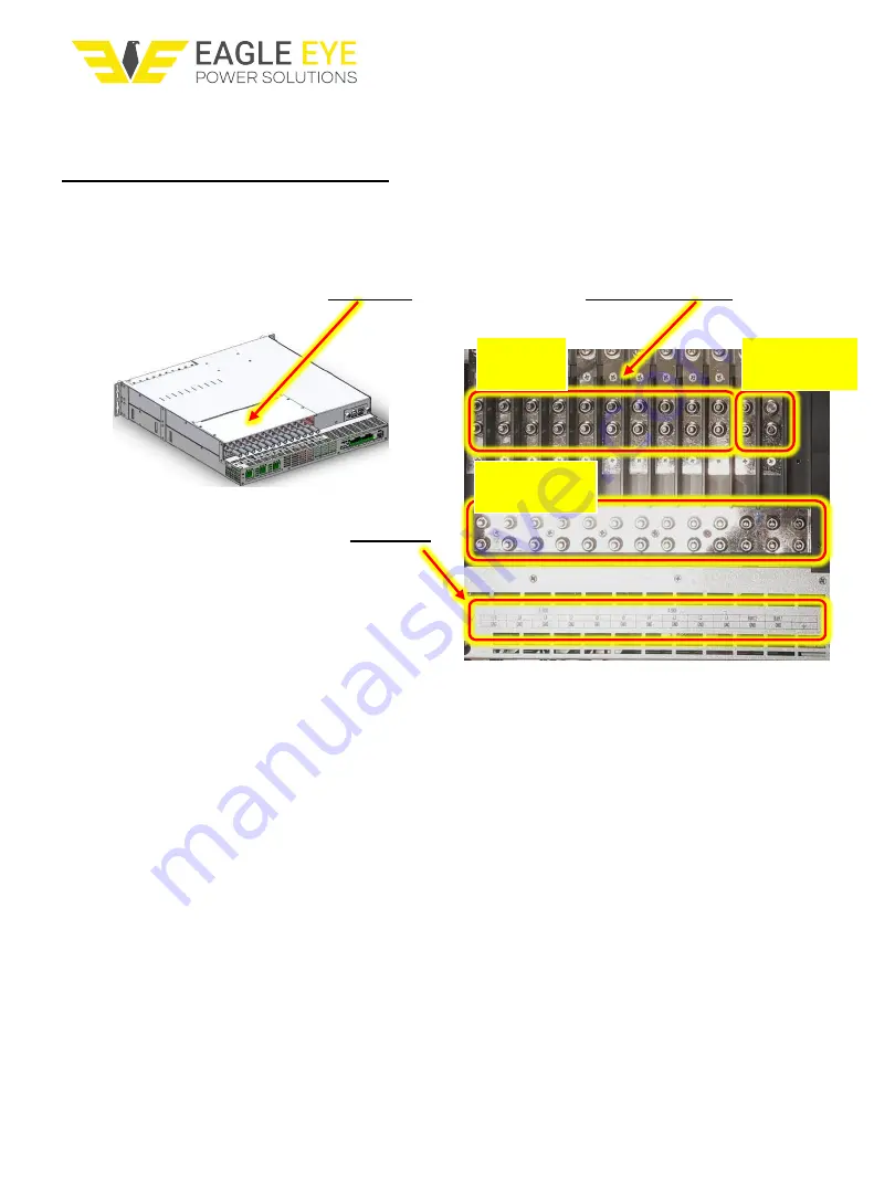
L10-L1
terminals
Batt1, Batt2
terminals
3.2
DC Output Cable Connections
Ensure that AC power to the shelf is off. If Batt1 or Batt2 circuit breakers are installed, turn them
to the OFF position. Remove the
rear cover
to gain access to the
DC terminal block
Each L1-L10, Batt 1, Batt 2, and GND/Return
cable connection should match the
silkscreen
If there are cables installed at either Batt1
or Batt2 terminals, use extreme caution as
these are live (direct connections) from the
external Battery string(s) for BBU, if equipped.
The minimum wire size for each of the
DC Output and Batt1, Batt2 cables is:
▪
L1 ~ L10 (-54V Output): 25mm
2
(AWG 4)
Figure 6. DC Output & Battery Terminal Block
(top view with cover removed)
▪
DC Output GND (Return for L1 ~ L10): 25mm
2
(AWG 4)
▪
Batt1, Batt2 (-54V): 35mm
2
(AWG 2)
▪
Batt1 GND, Batt2 GND: 35mm
2
(AWG 2)
Connect DC (-54V) cables with the straight-barrel 2-hole lugs to the breaker-protected L1-L10
(Load) and Batt 1, Batt 2 (Battery) nodes. Also, all of the Load Return and Batt Return cables
should include straight-barrel 2-hole lugs to connect to the common GND terminal block.
Replace the rear cover and secure it in place with the mounting hardware.
Note that the L1 ~ L10 DC bus positions are designed to carry 100A continuous current. However, this section
limits DC breakers up to 50A maximum due to existing availability. Currently, no 1RU breakers are available
with ratings > 50A but, if they become available in same form, fit and function, this section will be edited to
include higher rated breakers up to 100A, if possible.
GND (Return)
terminals


