1
8
AVI Slide Rev - C
Troubleshooting
Gate stops and
reverses direction in
mid cycle and the
OVERLOAD LED
remains ON.
(A) Gate operator is not plumb and level.
(B) ERD current sensor may be set too sensitive.
(C) Gate encountered an obstruction while cycling.
(A) The radio receiver’s LED remains on.
(B) One or more of the global input LEDs remain active.
(C) Gate has re-opened because it encountered an obstruction
while closing.
(D) The loop detector LED is on.
(E) CLOSE TIMER is not functioning.
(A) The radio receiver or remote control has
malfunctioned in the “ON” position.
(B) Check input/output connections for a short circuit.
(C) Only #3 “Key” input will resume normal operation.
(D) Reset loop detector. Verify correct loop wiring. Set loop
detector to a different frequency and/or change the sensitivity
of the loop detector.
(E) Be sure Switch #4 is in the “ON” position.
(A) Motor Overload LED is on.
(B) Radio receiver is not “ON” when the remote control
button is activated.
(C) The green “Power” LED is off.
(D) The Fuse is blown.
• Feature selector Switch #1 MUST be set to the “MASTER” (ON) position unless the operator is being used as a slave operator.
• Safety external loop detectors must be connected to the #2 “REVERSE LOOP” input (see pages 15 & 16).
• If the CLOSE TIMER feature is desired, Feature selector Switch #4 MUST be in the “ON” position (see page 11).
• It is OK to call the Eagle Access Customer Service Department with any questions... we are here to serve YOU!
1-800-708-8848
(A) Motor’s built-in thermal breaker has been tripped, let motor
cool down, try again.
(A) Gate is too heavy.
(B) Radio receiver has malfunctioned in the “OFF” position.
(C) Turn ON operator power switch and/or reset the main circuit
breaker.
(D) Check and/or replace the fuse with same amp fuse.
(A) Remount operator.
(B) Turn the ERD current sensor slightly in the clockwise
direction.
(C) Check and remove all obstructions
Gate will not close.
Gate will not open.
SYMPTOMS
PROBABLE CAUSE
COMMON OVERSIGHTS TO BE AWARE OF:
REMEDY
MOTOR 15A
OPENING
TIMER
ERD CONTROL
MULTI FUNCTION
GATE STATUS
FEATURE SELECTOR
M/S PHASE
1
0
CLOSING
MASTER
OPEN RIGHT
BRAKE ON
CLOSE TIMER ON
SLAVE
OPEN LEFT
BRAKE OFF
CLOSE TIMER OFF
1
ON
2
3
4
OFF—ON
SELECT
MIN
MAX
OPEN
LIMIT
ERD OVERLOAD
OPENING CLOSING CLOSED
LIMIT
SLAVE MASTER
+ –
+ –
#9
#8
+ MAGLOCK
- 24 VDC
#5
+ ALARM
- 12 VDC
#6
REVERSE
LOOP
#2
POWER
24V
AC
#7
KEY
#3
M-FCN
#4
GND
GND
RCVR
24VAC
#1
COMM PORT
INPUT/OUTPUT
RECEIVER
ERD
M/P
RESET
1
O
N
2
ON ON STOP N/C
ON OFF CLOSE
OFF ON PHANTOM
OFF OFF EDGE SENSOR
S1 S2 FCN
COMM PORT
POWER
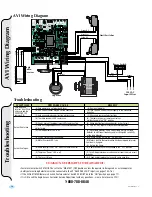
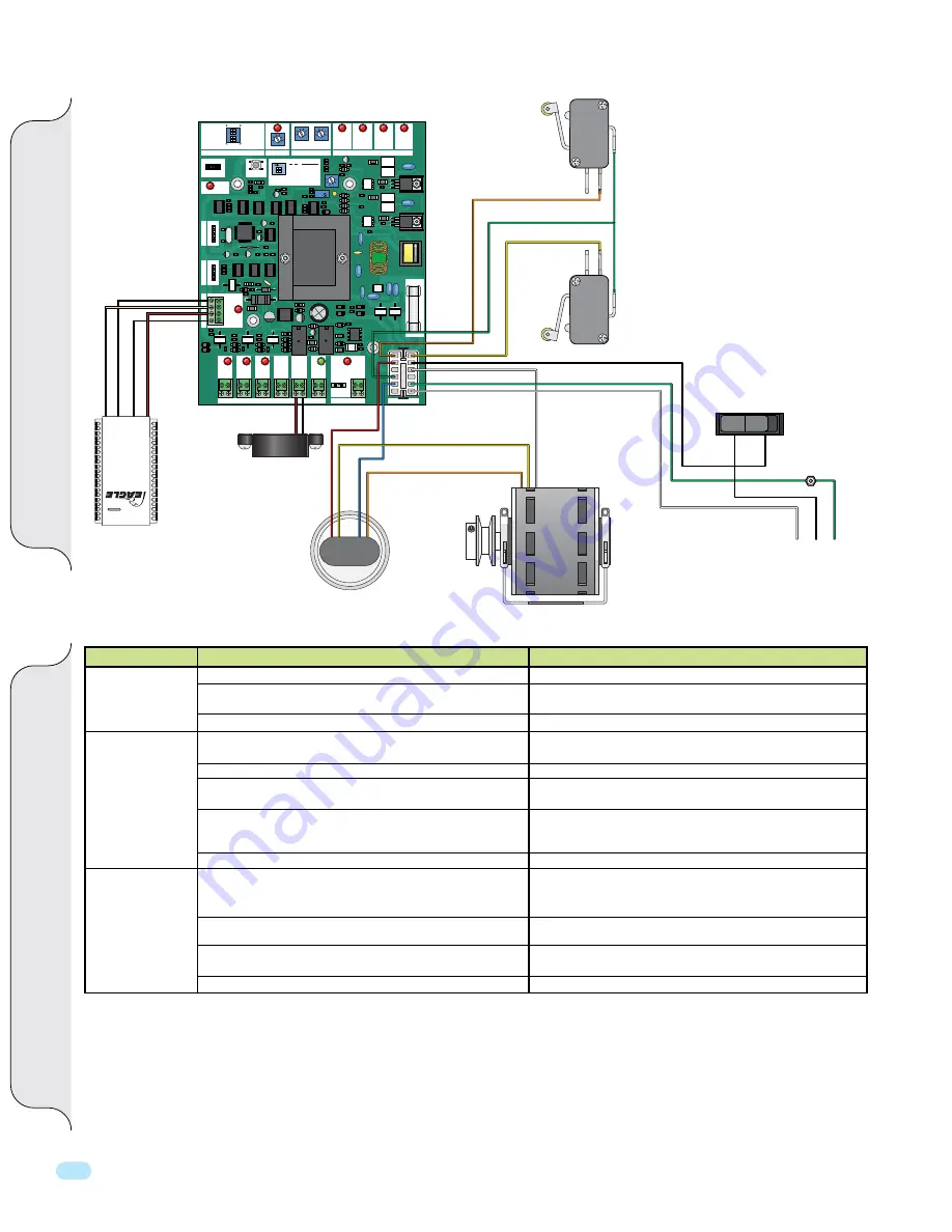
AVI Wiring Diagram
Red
Black
Capacitor
Yellow N.O.
Limit Switches
Orange N.O.
Green Com
Alarm
White
Red
Blue
Yellow
Orange
1/2 HP
Motor
Power Switch
120 VAC
Input Wires
White
Black
Green
White
Green
Black
Black
OFF ON
Ground
Blue
Y
ellow
Red
Black
Eagle
Radio
Receiver
A
VI W
iring
Diagr
am
Troubleshooting
Summary of Contents for AVI
Page 2: ...2 AVI Slide Rev C ...
Page 23: ...21 AVI Slide Rev C NOTES ...


