background image

27

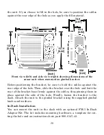
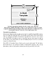
also make sure there is enough room behind the unit to attach the
power and transducer cables. (A drawing on the next page shows the
dimensions of a gimbal-mounted sonar unit.)

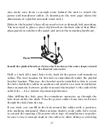
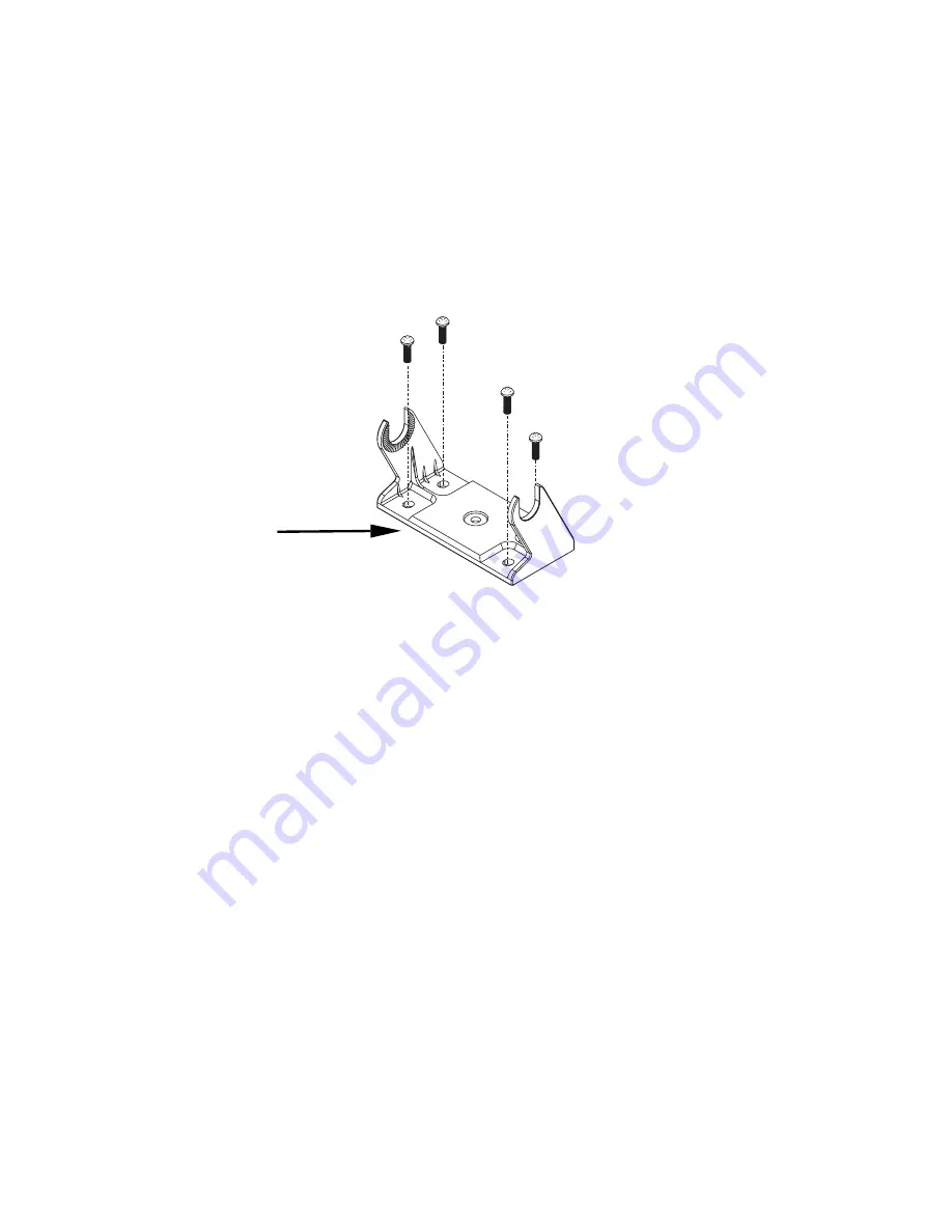
Holes in the bracket's base allow wood screw or through-bolt mounting.
You may need to place a piece of plywood on the back side of thin fiber-
glass panels to reinforce the panel and secure the mounting hardware.

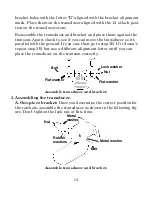
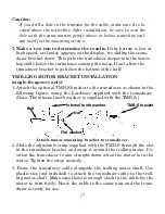
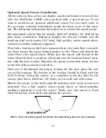
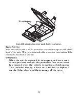
Install the gimbal bracket. Orient the bracket so the arms slope toward

the front of your unit.

Drill a 1-inch (25.4 mm) hole in the dash for the power and transducer
cables. The best location for this hole is immediately under the gimbal
bracket location. This way, the bracket can be installed so that it covers
the hole, holds the cables in position and results in a neat installation.
Some customers, however, prefer to mount the bracket to the side of the
cable hole — it's a matter of personal preference.

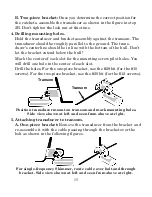
After drilling the hole, pass the transducer connector 

up

 through the

hole from under the dash. Pass the power cable's bare-wire end 

down

though the hole from the top.

If you wish, you can fill in the hole around the cables with a good ma-
rine caulking compound. (Some marine dealers stock cable hole covers
to conceal the opening.) No matter what type of installation you prefer,
be sure to leave enough slack in the cables to allow tilting or swiveling
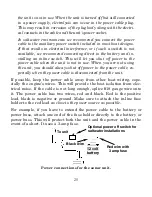
Front

Summary of Contents for FISHMARK 320

Page 1: ...Pub 988 0143 661 www eaglesonar com FishMark 320 and SeaFinder 320DF Fish finding Depth Sounding Sonars Installation and Operation Instructions...

Page 2: ...regulations and special offers at any time We reserve the right to do so without notice All features and specifications subject to change without notice All screens in this manual are simulated On th...

Page 3: ...ull Preparation and Installation 19 Speed Temperature Sensors 21 Power Connections 24 Mounting the Unit Bracket In Dash or Portable 26 Bracket Installation 26 In Dash Installation 28 Portable Installa...

Page 4: ...64 Reset Water Distance 65 Screen Contrast and Brightness 65 Sensitivity Auto Sensitivity 65 Set Keel Offset 67 Set Language 69 Software Version Information 69 Sonar Color Mode 70 Sonar Chart Display...

Page 5: ...o that you don t have to read the whole thing from front to back for the information you want At the start or end of each segment we ll tell you what content is coming up next If it s a concept you re...

Page 6: ...Now if you re into the fine details glance over the next segment on specifications to see just how much sonar power your unit contains It s important to us and our power users but if you don t care ho...

Page 7: ...p to 70 mph 61 kts Watts 1 500 watts peak to peak 188 watt RMS Sonar sounding depth capability SeaFinder 320DF 1 500 feet 450 meters FishMark 320 800 feet 244 meters Actual capability depends on trans...

Page 8: ...receiver and display In simple terms here s how it finds the bottom or the fish The transmitter emits an electrical impulse which the transducer con verts into a sound wave and sends into the water T...

Page 9: ...ital letters in a bold sans serif type like this DEPTH CURSOR These indicate that you are to select this command or option from a menu or take an action of some kind with the menu item Text that you m...

Page 10: ...Step 2 would mean Press the right arrow key for dual frequency units or press the right arrow key followed by the down arrow key for single frequency units to select highlight the Fish ID symbols com...

Page 11: ...ation of your battery or other power connection along with the power cable route 4 Install the transducer and route the transducer cable to the sonar unit 5 Install the power cable and route it to the...

Page 12: ...grade above or below waterline caulking compound The following installation types also call for these recommended tools and required supplies supplies are not included Single frequency transom install...

Page 13: ...ts face pointing straight down if possible 3 If the transducer is mounted on the transom make sure it doesn t interfere with the trailer or hauling of the boat Also don t mount it closer than approxim...

Page 14: ...the water as you cross waves or wakes Move the transducer a little lower to help prevent this If you cruise or fish around lots of structure and cover your transducer may be frequently kicking up from...

Page 15: ...parts first place the transducer s bracket against the transom and see if you can move the transducer so that it s parallel with the ground The following instructions sometimes vary depending on the...

Page 16: ...bracket with the letter A aligned with the alignment mark molded into the bracket Place the ratchets onto the transducer with the letter A aligned with the 12 o clock position on the transducer stem T...

Page 17: ...som Again check to see if you can move the transducer so it s parallel with the ground If you can then go to step 3A If it doesn t repeat step 2A but use a different alignment letter until you can pla...

Page 18: ...d If you can then go to step 3B If it doesn t repeat step 2B but use a different alignment letter until you can place the transducer on the transom correctly Assemble transducer and bracket 3 Assembli...

Page 19: ...the mounting screw pilot holes You will drill one hole in the center of each slot Drill the holes For the one piece bracket use the 29 bit for the 10 screws For the two piece bracket use the 20 bit fo...

Page 20: ...er to transom Rear view of dual frequency Skimmer shown 6 Route the transducer cable through or over the transom to the sonar unit Make sure to leave some slack in the cable at the transducer If possi...

Page 21: ...ch the optional TMB S bracket to the transducer as shown in the following figure using the hardware supplied with the transducer Note The internal tooth washer is supplied with the TMB S Attach motor...

Page 22: ...s on your display it could be because the transducer is not parallel with the ground when the boat is at rest in the water or at slow trolling speeds Transducer angles and their effects on fish arches...

Page 23: ...transducer installation can be made on hulls with flotation materials such as plywood balsa wood or foam between layers of fiberglass if the material is removed from the chosen area Epoxy the transdu...

Page 24: ...transducer out of the water and place it in the water in the sump of the boat Observe the sonar signal to see if there is a no ticeable decrease in sensitivity The second bottom signal may disap pear...

Page 25: ...etween the hull and transducer After the epoxy dries route the cable to the sonar unit Speed Temperature Sensors This unit can accept as many as two temperature sensors which can be used to monitor th...

Page 26: ...sensor See the following wiring diagram for temperature and speed sensor combinations Sonar unit with secondary external temperature sensor Sonar unit with external speed sensor or combo speed temp se...

Page 27: ...nt the sensor behind strakes or ribs These will disturb the water flow to the speed sensor Make sure the sensor will remain in the water when the boat is on plane Also make sure the location doesn t i...

Page 28: ...ade above or below waterline seal ant used for the screws The sensor is now ready for use Connect the sensor to the accessory socket on the back of your unit If you have any questions concerning the i...

Page 29: ...to the power cable es pecially when the power cable is disconnected from the unit If possible keep the power cable away from other boat wiring espe cially the engine s wires This will provide the bes...

Page 30: ...sonar unit on the top of a dash with the supplied gimbal bracket It can also be installed in the dash or mounted on a portable power supply If you use the supplied bracket you may be interested in the...

Page 31: ...cation for this hole is immediately under the gimbal bracket location This way the bracket can be installed so that it covers the hole holds the cables in position and results in a neat installation S...

Page 32: ...e bracket over the hole and butt the rear of the bracket base firmly against the cables thus pinning them in place against the side of the hole Finally fasten the bracket to the dash Attach the unit t...

Page 33: ...table power pack The power pack and an optional portable transducer expand the uses for your sonar unit The PPP 13 makes it easy to use the unit on your boat or take it to the dock on a float tube on...

Page 34: ...is intended for use when your unit and the vehicle it s mounted in are idle WARNING When the unit is mounted in an unprotected area such as an open boat cockpit the protective face cover must be remo...

Page 35: ...more advanced functions and utilities The material in Sec 4 is arranged in alphabetical order Before you turn on the unit it s a good idea to learn about the different keys the Main Menu the Sonar Men...

Page 36: ...it key lets you return to the previous screen clear data or erase a menu 7 ALARM The Alarm key is a quick shortcut to the sonar alarms menu It allows you to choose which alarms to use and when 8 ZOUT...

Page 37: ...ntrol its operation They are the Main Menu the Sonar Menu and the Pages Menu Main Menu The Main Menu contains some basic function commands and some setup option commands You access the Main Menu by pr...

Page 38: ...when the sonar sees a fish You can also set deep or shallow depth alarms and zone alarms Popup Help command turns the pop up help boxes on or off When you select a menu command these information boxe...

Page 39: ...the op erating software is loaded in your unit Sonar Menu The Sonar Menu contains commands for the major sonar features and options You access the Sonar Menu by pressing the MENU key one time You run...

Page 40: ...line on the sonar chart which allows you to accurately measure the depth of a sonar target Overlay Data command chooses what types of information such as water temperature to show overlaid on the son...

Page 41: ...w of the water column beneath the boat The chart moves across the screen displaying sonar signal echoes that represent fish structure and the bottom Sonar Page showing full sonar chart mode Surface cl...

Page 42: ...es and other data are dis played in many ways We ll discuss all of those features and options in Section 4 but to show you how easy the sonar unit is to operate see the following 10 step quick referen...

Page 43: ...y Menu will appear on the left of your screen Use and to change the setting Boosting sensitivity will show more information on your screen which may cause clutter Reducing sensitivity will filter out...

Page 44: ...reen Decreasing the sensitivity can reduce the clutter and show the strongest fish echoes if fish are present As you change the sensitivity setting you can see the difference on the chart as it scroll...

Page 45: ...he bottom signal may completely disappear from the screen when you reduce sensitivity to about 50 percent or less These figures show results of different sensitivity levels on the same location Fig 1...

Page 46: ...ress MENU to AUTO SENSITIVITY ENT to SENSITIVITY ENT Press or to pick a different sensitivity setting When it s set at the desired level press EXIT Important Tip While you are experimenting and learni...

Page 47: ...that lunker swims under your boat you ll hear it Fish I D can also be useful when you want to screen out some of the sonar detail gathered by your unit For example in one case fishermen in San Franci...

Page 48: ...tomers This PC application simulates the actual sonar unit on your computer You can run it from your computer keyboard or use your mouse to press the virtual keys Easy download and installation instru...

Page 49: ...es passing over the face of the transducer even vibration from the engine In all cases noise can produce unwanted marks on the display The ASP feature has four settings Off Low Medium and High If you...

Page 50: ...allow and a Deep setting Only the bottom signal will trigger this alarm This is useful as an anchor watch a shallow water alert or for navigation Depth Alarms The depth alarms sound a tone when the bo...

Page 51: ...ep alarm 1 Press ALARM 2 Press to DEEP ALARM ENABLED to DEEP ALARM DEPTH ENT 3 Press or to change the first number then press to move the cursor to the next number and repeat until the depth is correc...

Page 52: ...alarm 6 To turn off the alarm press ALARM to ZONE ALARM EN ABLED ENT EXIT To switch to a different depth setting open the Sonar Alarms menu and repeat the instructions in steps 3 and 4 above Fish Ala...

Page 53: ...the first character or then press to move the cursor to the next number and repeat until the percentage is correct then press EXIT Chart Speed The rate that echoes scroll across the screen is called t...

Page 54: ...art speed 3 When it s set at the desired level press EXIT Contrast See the entry in this section for Screen Contrast and Brightness Depth Cursor The depth cursor consists of a horizontal line with a d...

Page 55: ...RANGE ENT 2 The Depth Range Control Scale appears Press or to select a dif ferent depth range A black bar highlights the selected range Range numbers in gray cannot be selected 3 When the new range is...

Page 56: ...kes it useful for ice fishing or when you re fishing at anchor When the boat is not moving fish sig nals are long drawn out lines on a normal chart display FasTrack con verts the graph to a vertical b...

Page 57: ...u may see fish symbols on the screen when actually there are no fish The reverse is also true The illustrations on the next page show how Fish I D can actually miss fish that are present Does that mea...

Page 58: ...re replaced with symbols To turn the Fish I D feature on 1 From the Sonar Page press MENU to SONAR FEATURES ENT 2 Press or to FISH ID SYMBOLS ENT EXIT EXIT To turn off Fish I D repeat the instructions...

Page 59: ...to FISH ID DEPTHS ENT EXIT EXIT To turn off FishTrack repeat the instructions in step 1 Turning off FishTrack in this manner will not turn off Fish I D symbols Sonar Features menu with Fish I D Depths...

Page 60: ...in between vary in gray in proportion to their signal strength The Grayline control determines the range for black to white Also note that when using FishReveal we recommend that you turn off Auto Se...

Page 61: ...its dual frequency transducer which operates with both 200 kHz and 50 kHz The 200 kHz frequency has a 12 cone angle and the 50 kHz frequency has a 35 cone angle The default frequency is 200 kHz which...

Page 62: ...o 50 kHz 1 From the Sonar Page press MENU to SONAR FEATURES ENT 2 Press to 50 KHZ ENT 3 Press EXIT EXIT to clear the menu Grayline Grayline lets you distinguish between strong and weak echoes It paint...

Page 63: ...the Grayline level 1 From the Sonar Page press MENU to GRAYLINE ENT 2 The Grayline Control Bar appears Press to decrease Grayline press to increase Grayline 3 When it s set at the desired level press...

Page 64: ...rocky bottom the drop offs with a wider gray line The muddier bottom below those drop offs appears as a narrower gray line HyperScroll See the entry on Ping Speed which controls the HyperScroll featur...

Page 65: ...ous unchecked po sition If you wish you may now use or to select other Data Types to turn off 2 To return to the previous page press EXIT EXIT To change displayed data font size 1 Press MENU to OVERLA...

Page 66: ...and the Water Speed of the boat Ping Speed HyperScroll Ping Speed controls the rate at which the transmitter and transducer broadcast sonar sound waves pings into the water The unit has a default ping...

Page 67: ...ENU to PING SPEED ENT 2 The Ping Speed Control Bar appears Press to increase ping speed press to decrease ping speed When it s set at the desired level press EXIT To adjust Sensitivity 1 From the Sona...

Page 68: ...ess ENT to check it turn on and uncheck it turn off After the option is set press EXIT to return to the page display Pop up Help message for the Calibrate Water Speed command Reset Options This comman...

Page 69: ...elected Press or to move the bar The left end of the scale is minimum contrast the right end is maximum contrast To adjust the display s brightness 1 Press to BRIGHTNESS Press or to move the bar The l...

Page 70: ...column In that case a decrease in sensitivity is indicated to reduce some of the clutter The control bar used to adjust sensitivity up or down is the same whether the unit is in the automatic or manua...

Page 71: ...Bar on the screen as the chart scrolls You can see the changes on the screen as you press the up or down arrows This is handy when there s a lot of clutter in the water and you are matching the sensit...

Page 72: ...irst number then press to change the number to 3 4 Press to the second number then press to change the number to 5 then press EXIT The depth indicators now accurately show the depth of water beneath t...

Page 73: ...enus now appear in the language you selected Software Version Information From time to time Eagle updates the operating system software in some of its products These software upgrades are usually offe...

Page 74: ...Press or to Mode Name ENT 4 Press EXIT EXIT to return to the Sonar Page Sonar Chart Display Options The Pages Menu offers four chart display options for dual frequency models and three options for si...

Page 75: ...r on the far right shows the area that s zoomed when the zoom is in use See the Zoom section for more information Full Sonar Chart The Overlay Data depth and water temperature are both set to the smal...

Page 76: ...kHz view at left and 200 kHz view at right You can adjust the sensitivity in each window To adjust sensitivity in auto mode 1 Press MENU ENT 2 The unit asks which you wish to adjust Press or to selec...

Page 77: ...r Digital Data Chart Customizing the Digital Data Chart Screen The Digital Data Chart screen can be customized to show digital data different from the defaults first shown To customize this screen 1 F...

Page 78: ...e press MENU MENU to SONAR SIMULATOR ENT 2 Turn off Sonar Simulator by pressing MENU MENU to SONAR SIMULATOR ENT EXIT NOTE If you turn on your unit before attaching a transducer it may enter a demo mo...

Page 79: ...ceiver decreasing it near the surface and gradually increasing it as the depth increases There are three levels of surface clarity available low medium or high It can also be turned off The default le...

Page 80: ...Distance Unit of Measure Press or to change the Speed Distance then press ENT After the option is set press EXIT EXIT EXIT to return to the page display Zoom Zoom Bar Zooming the display is a common...

Page 81: ...he display to the normal mode At left Sonar Page normal view Center same view zoomed to 2X Right same view zoomed to 4X Zoom Pan Your unit has the handy ability to quickly zoom in on any portion of th...

Page 82: ...78 Notes...

Page 83: ...olts If it isn t the wiring to the unit is defective the battery terminals or wiring on the terminals are corroded or the bat tery needs charging Unit operates only in demo mode 1 The transducer has n...

Page 84: ...y It may change the range to limits far greater than the water you are in If this happens place the unit in the manual mode then change the range to a realistic one for example 0 100 feet and increase...

Page 85: ...re detail 4 The boat must be moving at a slow trolling speed to see fish arches If the boat is motionless fish stay in the cone showing on the screen as straight horizontal lines NOISE A major cause o...

Page 86: ...ngine Increase the RPM with the gearshift in neutral If noise ap pears on the display the problem could be one of three things spark plugs alternator or tachometer wiring Try using resistor spark plug...

Page 87: ...83 Notes...

Page 88: ...84 Notes...

Page 89: ...uct THIS REPAIR OR REPLACEMENT OR REFUND AS JUST DESCRIBED IS THE EXCLUSIVE REMEDY AVAILABLE TO YOU AGAINST US FOR ANY DEFECT MALFUNC TION OR NON CONFORMITY CONCERNING THE PRODUCT OR FOR ANY LOSS OR D...

Page 90: ...hange or end our shipping policies regulations and special offers at any time We reserve the right to do so without notice in Canada If you re in Canada and you have technical return or repair questio...

Page 91: ...com 3 Canadian customers can write Lowrance Eagle Canada 919 Matheson Blvd E Mississauga Ontario L4W2R7 or fax 905 629 3118 Shipping Information If it becomes necessary to send a product for repair o...

Page 92: ...Visit our web site www eaglesonar com Eagle Pub 988 0143 661 Copyright 2002 All Rights Reserved Printed in USA 101702 Eagle Electronics...

Reviews: