background image


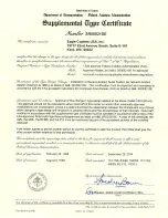
19717 62

ND

 Ave. South, Suite E-101,  Kent, WA 98032       Tel: 800 546 2210 or +1 253 395 9105        Fax 800 546 2220 


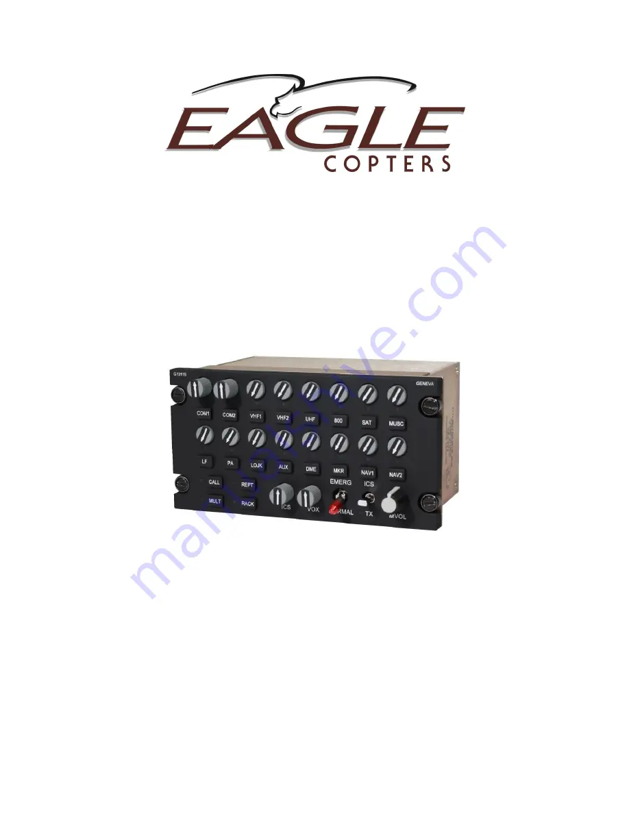
P139-HD 


DIGITAL AUDIO SYSTEM 


BELL 206 / 407 

INSTALLATION 


MDL GA182 Rev M     STC SR00521SE 


Summary of Contents for P139-HD

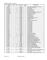
Page 1: ...19717 62 ND Ave South Suite E 101 Kent WA 98032 Tel 800 546 2210 or 1 253 395 9105 Fax 800 546 2220 P139 HD DIGITAL AUDIO SYSTEM BELL 206 407 INSTALLATION MDL GA182 Rev M STC SR00521SE ...

Page 2: ......

Page 3: ...o be the exclusive property of Eagle whether or not disclosed to or entrusted to the custody of Recipient Recipient further hereby acknowledges that all Proprietary information and materials have been disclosed or made available to him solely for the purpose of assisting him in incorporating using or maintaining equipment provided by Eagle Recipient hereby agrees not to disclose or allow to be dis...

Page 4: ......

Page 5: ......

Page 6: ......

Page 7: ......

Page 8: ......

Page 9: ...e Routing AS350 AS355 Audio System G11262 4 D 9 5 98 1 Wire Routing AS350 AS355 Audio System G11262 5 9 5 98 1 Wire Routing AS350 AS355 Audio System G11262 6 D 9 5 98 1 Wire Routing AS350 AS355 Audio System G11262 7 9 5 98 1 Wire Routing AS350 AS355 Audio System G11262 8 9 5 98 1 Wire Routing AS350 AS355 Audio System G11268 3 14 03 1 Backplane G11269 F 9 30 08 1 Headset Control Cable G11287 A 7 24...

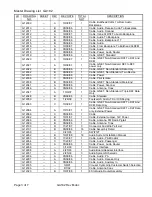
Page 10: ...10 03 1 Control Panel G11475 6 10 03 1 Control Panel G11480 A 7 29 04 1 Control Panel G11481 6 10 03 1 Control Panel G11482 6 10 03 1 Control Panel G11490 7 29 04 1 Control Panel G11694 A 6 17 98 1 FM Antenna Interface G11695 D 10 07 08 1 Aft Audio Connector Box G11695 1 E 10 07 08 1 Aft Audio Box Top G11695 2 D 10 07 08 1 Aft Audio Box Bottom G11697 1 C 9 5 98 1 ENG System Panel Layout G11697 2 9...

Page 11: ...er Scanner G12046 A 05 09 06 1 Cable Antenna Coax G12047 A 10 9 07 1 Cable GNET Non Standard Triple D9F Data Only G12048 B 05 09 06 1 Cable Shielded G12050 C 1 29 09 1 Footswitch Audio TX or ICS Keying G12063 C 10 09 07 1 Cable GNET Non Standard D9F To D9F And D9M Data Only G12064 A 10 10 07 1 Cable GNET Non Standard D9F To D9F Data only External Power G12088 C 05 09 06 1 Cable G12092 B 10 31 07 1...

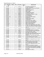
Page 12: ...dio Connections G12589 B 07 12 06 1 Cable Audio MW Audio Ctrl To MW Expander And Troll G12590 B 10 10 07 1 Cable Audio MW Expander Out To BrightEye 30 Analog In G12597 B 11 09 07 1 Cable Audio Expander J2 To VU Meter G12598 B 10 24 07 1 Cable BE54 Audio Out to Audio Backplane G12467 B 11 09 07 1 Cable Audio D9F To XLR3F G12603 A 9 30 08 1 Bell 206 407 Aft Passenger Audio G12604 8 17 05 1 Passenger...

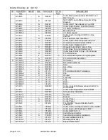
Page 13: ...ystem Wiring Diagrams G13005 A 10 07 09 1 P139 HD AS350 Installation X G13005 1 A 4 08 13 1 Hat Section G13005 2 A 10 07 09 1 Back Plate Assembly G13005 3 10 30 08 1 Shim G13005 4 A 10 07 09 1 Back Plate G13005 5 A 10 07 09 1 Clip G13006 A 4 11 12 1 P139 HD Bell 206 407 Installation G13006 2 B 1 13 12 1 Clip G13006 4 A 1 13 12 1 Doubler G13009 1 13 12 1 Tray Assy G13009 1 A 4 11 12 1 Tray G13009 2...

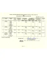
Page 14: ...BLE TRACKING OF REVISIONS BY SHEET No DCF D 7 10 98 G11262 All pages G11306 Sht 1 G11697 Sht 1 CORRECTED REFERENCE DESIGNATORS CLARIFIED WIRE ROUTING DESCRIPTIONS STA No S LOCATION OF SWIF 12 MODULE POSITION OF CO PILOT S HEADSET JACKS GLH E 10 21 98 ALL Revised GA182 2 GA182 4 GA1 2TP G10063 G11261 G11262 G11306 and G11697 Added new GA1 8TP GA1 9TP G10063 G11306 G11321 G11322 G11350 G11435 G11708...

Page 15: ...val Incorporated ECO s 1448 1453 1471 1483 CLB K 5 15 2012 ALL Removed ICA s and RFMS from MDL as these are approved independently from the MDL Incorporated ECO 1495 and ECO 1498 adding the EC135 and EC145 models to the AML CLB L 12 03 2012 ALL Incorporated ECO 1442 adding the Bell 204 205 212 214 412 models to the AML Incorporated ECO 1503 CLB M 6 13 2013 ALL Removed EC145 Model and Bell 204 205 ...

Page 16: ......

Page 17: ......

Page 18: ... Revised labeling notes to engineering standards G13116 Revised labeling notes to engineering standards G13121 Corrected part number on back shell on sht 2 ECO DOCUMENT LIST NOTE X in CH change column indicates change from last revision level Documents with multiple pages that have a different revision level on some pages are listed by individual pages on this list CH DOC No PAGES REV DATE DESCRIP...

Page 19: ......

Page 20: ...G13160 and is a Three board router This installation replaces wiring drawing G13004 with drawing G13162 Installation of this router is performed the same as the others two routers with slight changes in the mounting hardware as noted in the instructions The G13160 router supports more radios control panels and headsets than what the G13000 provides This change is considered a minor change since th...

Page 21: ...GA182 7 17 D 4 23 14 P139 HD Installation Instructions AS350 355 X GA182 8 16 D 4 23 14 P139 HD Installation Instructions Bell 206 407 X GA182 11 18 D 4 23 14 P139 HD Installation Instructions EC135 X G13004 13 H 4 24 14 P139 HD Audio System Wiring Diagrams X G13160 1 12 9 13 P139 HD 3 Board Router X G13161 1 12 12 13 Wide Tray Assy X G13161 1 1 12 12 13 Wide Tray X G13161 2 1 12 12 13 Wide Brace ...

Page 22: ......

Page 23: ......

Page 24: ......

Page 25: ...iled Explanation This ECO updates Audio Routers G13000 and G13160 to change the operating voltage from 10 30 VDC to 14 32 VDC ECO DOCUMENT LIST NOTE X in CH change column indicates change from last revision level Documents with multiple pages that have a different revision level on some pages are listed by individual pages on this list CH DOC No PAGES REV DATE DESCRIPTION X G13000 1 E 8 13 14 P139...

Page 26: ......

Page 27: ......

Page 28: ......

Page 29: ......

Page 30: ......

Page 31: ......

Page 32: ......

Page 33: ......

Page 34: ......

Page 35: ...Geneva Aviation Inc www GenevaAviation com GA182 8 Rev D P139 HD Digital Audio System 1 of 16 GA182 8 Revision D 4 23 2014 P139 HD Digital Audio System Bell 206 407 Installation Manual ...

Page 36: ...ess IAW AC 43 13 1b Chapter 11 Section 8 Paragraph 11 96 D Clamp wiring harness IAW AC 43 13 1b Chapter 11 Section 11 Paragraph 11 146 E Clamp and route wiring harness around movable controls IAW AC 43 13 1b Chapter 11 Section 9 Paragraph 11 125 F Wiring and harness to be separated IAW AC 43 13 1b Chapter 11 Section 8 Paragraph a 11 105 11 106 G Install service loops at harness terminations IAW AC...

Page 37: ...ons 1 4 Prior to installation of this system it is the responsibility of the installer to confirm by analysis or measurement that the additional power requirement will not exceed the capacity of the avionics bus or the aircraft s electrical system Power consumption for this audio system is 5 amps at 28 volts The system is designed to use redundant power sources both coming from the master avionics...

Page 38: ...y reference to the drawing that defines the cable construction details The installer may at the installer s discretion substitute connectors wire type and connection details so long as the final installations operate correctly and meets FAA standards 1 9 The Router features a COM1 Isolate mode that automatically connects the pilot s headset and mic switches directly to COM1 in the event of power l...

Page 39: ...system The installer may at the installer s discretion add or remove radios control panels headset groups or ICS and Transmit PTT switches as needed 2 2 Control Panels G13115 and G13116 may be used interchangeably depending on the control functions desired and number of radios installed 2 3 It is the installer s responsibility to document the system configuration as installed for maintenance purpo...

Page 40: ... Aviation Inc www GenevaAviation com GA182 8 Rev D P139 HD Digital Audio System 6 of 16 3 0 Component Installation Hookup J6 NETWORK PORT J7 MEMORY PORT J3 J1 J4 J2 J5 Figure 2 G13000 Router Connector Layout ...

Page 41: ...els 3 1 4 J4 is used to connect the Copilot s control panel Copilot s headset group headset groups 8 12 and additional passenger control panels 3 1 5 J5 is used to connect power ground Pilot s COM1 Isolate and Copilot s COM2 Isolate 3 1 6 J6 is a network port used for system configuration adjustment 3 1 7 J7 is a memory card slot used for storing system configuration data onto removable media 3 1 ...

Page 42: ...Geneva Aviation Inc www GenevaAviation com GA182 8 Rev D P139 HD Digital Audio System 8 of 16 J8 NETWORK PORT J9 MEMORY PORT J6 J5 J2 J1 J7 J3 J4 Figure 3 G13160 Router Connector Layout ...

Page 43: ...pilot s headset group headset groups 8 12 and additional passenger control panels 3 2 5 J5 is used to connect radios XCVR21 XCVR30 3 2 6 J6 is used to connect headset groups 13 18 and additional passenger control panels 3 2 7 J7 is used to connect power ground Pilot s COM1 Isolate and Copilot s COM2 Isolate 3 2 8 J8 is a network port used for system configuration adjustment 3 2 9 J9 is a memory ca...

Page 44: ...equipment The router is to be mounted Aft of the Fuel Cell area 3 3 3 Note for the G13160 Router replace in drawing G13006 the following items G13009 with G13161 G13009 3 with G13161 3 G13006 2 with G13161 4 and use 3 MS24693S51 screws to install use 2 NAS622CE2 Support Hooks Doubler G13006 4 with G13161 5 3 3 4 For Router G13000 refer to drawing G13004 for the detailed wiring schematic used in th...

Page 45: ... than there are available GNET ports on the router connect J1 of each control panel to a GNET port in parallel for pins 1 4 Pins 5 9 will be unique ID for each control panel connector See G13004 sheet 9 for details 3 4 3 The pilot control panel also controls the COM1 Isolate function Optionally the copilot control panel controls the COM2 isolate function See Section 1 8 for more information 3 5 Co...

Page 46: ... and optionally installer defined special functions The G13116NS version does not have an EMERG NORMAL switch and must not be used as a pilot or copilot primary panel 3 7 Headset Ports 3 7 1 The Pilot and Copilot Headset Group consists of the headset jack ICS switch and transmit switches on the cyclic and or foot switches 3 7 2 For each passenger a unique Passenger Headset Group is needed The Pass...

Page 47: ...onnects to J2 on the router along with radios XCVR12 XCVR20 refer to G13004 sheet 5 3 8 3 For the G13160 the following connections are available 3 8 3 1 The COM1 radio connects to J1 on the Router along with radios XCVR3 XCVR11 refer to G13162 sheet 5 3 8 3 2 The COM2 radio connects to J3 on the router along with radio ports XCVR12 XCVR20 refer to G13162 sheet 6 3 8 3 3 Radios XCVR21 XCVR30 connec...

Page 48: ...essories Activate ICS and confirm proper operation Place PILOT EMERG NORMAL switch in EMERG position Key transmit switch and confirm proper operation of COM1 4 3 Place the PILOT EMERG NORMAL switch in NORMAL position and check all transceivers receivers and audio devices 4 4 If the system is equipped with a COPILOT EMERG NORMAL switch repeat the steps in sections 4 2 and 4 3 for Copilot position a...

Page 49: ...ar its origin Confirm that the current draw during the above described test conditions is less than the current limiter fuse or circuit breaker rating for that branch circuit 5 5 If the current draw is greater than the current limiter rating it becomes the installer s responsibility to re distribute some of the other equipment powered by this branch circuit to another suitable branch circuit in or...

Page 50: ...rworthy prior to returning to service 8 0 FAA Requirements 8 1 Amend the weight and balance records and make the necessary log book entry Complete an FAA form 337 showing the installation of this equipment in accordance with the STC instructions and submit one copy to the FAA and one copy to the aircraft owner File all data and a copy of the STC with the aircraft records LOG OF REVISIONS REVISION ...

Page 51: ...GA1 2TP Rev C Page 1 of 7 GA1 2TP REV C 5 13 2012 EMI Test Procedure 19717 62 ND Ave South Suite E 101 Kent WA 98032 Tel 800 546 2210 or 1 253 395 9105 Fax 800 546 2220 ...

Page 52: ...ase GLH A 9 08 1997 2 Added LIST OF REVISIONS Page GLH B 10 16 1998 3 4 Added coverage for FADEC aircraft under Scope Revised procedure under Transponder test GLH C 5 13 2012 ALL Revised Scope to remove FADEC references Revised FAR references to CFR Updated checklist for other equipment Updated format of document to current standards CLB ...

Page 53: ...ing conducted with the aircraft in flight shall be performed with safety of flight in mind and with only necessary personnel on board Testing shall be conducted on the aircraft with all aircraft systems and equipment operating normally and cycled as necessary to conduct the test The EUT shall be operated normally The EUT shall be cycled on and off The EUT shall also be cycled through all of its op...

Page 54: ...__ Annunciator Indicators N A __ Pass __ Fail __ Flight Time Hour Meter N A __ Pass __ Fail __ Warning Horn N A __ Pass __ Fail __ Outside Air Temperature Indicator N A __ Pass __ Fail __ Transponder N A __ Pass __ Fail __ Set controls to mode C code 1200 or other code assigned by ATC Cycle EUT and confirm proper data transmitted either by use of transponder ground test equipment or by confirmatio...

Page 55: ...ng flight while established on an ILS glide slope Radio Altimeter N A __ Pass __ Fail __ Perform test with appropriate ground test equipment or check reading in flight The space below is provided to include additional systems or devices not listed previously These would include any Transceivers Nav Aids Radar or Auto Pilot systems Use the Manufacturers test procedures for each component listed wit...

Page 56: ...________________________________________________ ________________________________________________________________ Other Equipment _________________ N A __ Pass __ Fail __ Describe test _____________________________________________________ ________________________________________________________________ Other Equipment _________________ N A __ Pass __ Fail __ Describe test _________________________...

Page 57: ..._________________________________ __________________________________________________________________ __________________________________________________________________ __________________________________________________________________ __________________________________________________________________ Test performed by ________________________________________________ Name Credentials Test witnessed...

Page 58: ......

Page 59: ...TE G13000 9 Title THIS DOCUMENT INCLUDES INFORMATION PROPRIETARY TO GENEVA AVIATION AND SHALL NOT BE USED OR DUPLICATED BY ANYONE WITHOUT THE WRITTEN PERMISSION OF GENEVA AVIATION INC DATE CHECKED Design Drawing Number Pro No REV D SIZE UNLESS OTHERWISE SPECIFIED DIMENSIONS ARE IN INCHES TOLERANCES ARE FRACTIONS 1 8 DECIMAL X 050 XX 030 XXX 010 ANGLES 2 BREAK SHARP EDGES REVISIONS REV DESCRIPTION ...

Page 60: ......

Page 61: ... HEYCO HOLE PLUG 2603 Title THIS DOCUMENT INCLUDES INFORMATION PROPRIETARY TO GENEVA AVIATION AND SHALL NOT BE USED OR DUPLICATED BY ANYONE WITHOUT THE WRITTEN PERMISSION OF GENEVA AVIATION INC DATE CHECKED Design Drawing Number Pro No REV D SIZE UNLESS OTHERWISE SPECIFIED DIMENSIONS ARE IN INCHES TOLERANCES ARE FRACTIONS 1 8 DECIMAL X 050 XX 030 XXX 010 ANGLES 2 BREAK SHARP EDGES REVISIONS REV DE...

Page 62: ......

Page 63: ... HEYCO HOLE PLUG 2603 Title THIS DOCUMENT INCLUDES INFORMATION PROPRIETARY TO GENEVA AVIATION AND SHALL NOT BE USED OR DUPLICATED BY ANYONE WITHOUT THE WRITTEN PERMISSION OF GENEVA AVIATION INC DATE CHECKED Design Drawing Number Pro No REV D SIZE UNLESS OTHERWISE SPECIFIED DIMENSIONS ARE IN INCHES TOLERANCES ARE FRACTIONS 1 8 DECIMAL X 050 XX 030 XXX 010 ANGLES 2 BREAK SHARP EDGES REVISIONS REV DE...

Page 64: ......

Page 65: ...ON OF GENEVA AVIATION INC www genevaaviation com SHT DATE DATE DATE APPROVAL PRO NO DRAWN CHECKED DWG NO TITLE REV REVISION DESCRIPTION REV APPROVAL DATE G13004 H P139 HD AUDIO SYSTEM WIRING DIAGRAMS NOTES GA182 1 of 13 RBH 10 30 08 JSW 10 30 08 CLB 10 30 08 11 The Audio System works with a range of supply voltages as specified in the installation instructions Breaker ratings and wire sizes shown ...

Page 66: ... KEY RX 15 LO RX 15 HI RX 18 LO TX 15 HI TX 18 HI 23 39 5 37 4 21 38 22 6 TX 2 KEY TX 2 LO RX 12 HI 40 7 24 41 25 8 9 RX 12 LO TX 12 HI TX 16 LO TX 13 KEY 15 RX 19 LO TX 15 KEY TX 18 KEY TX 15 LO RX 16 HI RX 19 HI RX 16 LO TX 19 HI TX 16 HI TX 19 LO RX 13 LO 12 45 27 43 10 26 44 28 11 TX 12 KEY RX 13 HI 30 46 13 29 47 14 31 TX 13 HI TX 13 LO RX 20 HI TX 16 KEY TX 19 KEY TX 20 KEY RX 20 LO 33 49 48...

Page 67: ...EY 4 MIC 12 LO XMIT KEY 12 ICS KEY 11 HEADSET 12 LO XMIT KEY 11 MIC 11 LO HEADSET 11 LO MIC 10 LO ICS KEY 10 XMIT KEY 10 XMIT KEY 2 HEADSET 9 LO XMIT KEY 9 MIC 9 LO ICS KEY 9 ICS KEY 8 MIC 8 LO XMIT KEY 8 HEADSET 8 LO CPLT COM2 KEY ICS KEY 2 MIC 2 LO HEADSET 2 LO N C MIC 12 HI GNET 4 28V GNET 5 28V GNET 5 DATA HI GNET 4 DATA HI HEADSET 12 HI MIC 11 HI HEADSET 11 HI MIC 10 HI HEADSET 8 HI HEADSET 9...

Page 68: ... W W TX HI TX HI TX HI TX HI RX HI TX KEY TX LO RX LO RX HI TX KEY TX LO RX LO RX HI TX KEY TX LO RX LO RX HI TX KEY TX LO RX LO RX HI TX KEY TX LO TX HI RX LO TX HI TX HI TX HI TX HI TX HI RX HI RX LO TX LO TX KEY RX HI TX KEY TX LO RX LO RX HI TX KEY TX LO RX LO RX HI TX KEY TX LO RX LO RX HI TX KEY TX LO RX LO COM1 J1 P1 XCVR3 XCVR4 XCVR5 XCVR6 XCVR8 XCVR7 XCVR9 XCVR10 TX KEY11 D50F 6 3 THIS DO...

Page 69: ...W W W B W B W W TX HI TX HI TX HI TX HI RX HI TX KEY TX LO RX LO RX HI TX KEY TX LO RX LO RX HI TX KEY TX LO RX LO RX HI TX KEY TX LO RX LO RX HI TX KEY TX LO TX HI RX LO TX HI TX HI TX HI TX HI TX HI RX HI RX LO TX LO TX KEY RX HI TX KEY TX LO RX LO RX HI TX KEY TX LO RX LO RX HI TX KEY TX LO RX LO RX HI TX KEY TX LO RX LO COM2 J2 P2 XCVR12 XCVR13 XCVR14 XCVR15 XCVR17 XCVR16 XCVR18 XCVR19 D50F 6 ...

Page 70: ... XMIT KEY 5 ICS KEY 5 MIC 5 LO MIC 5 HI HEADSET 5 LO HEADSET 5 HI XMIT KEY 6 ICS KEY 6 MIC 6 LO MIC 6 HI HEADSET 6 LO HEADSET 6 HI XMIT KEY 7 ICS KEY 7 MIC 7 LO MIC 7 HI HEADSET 7 LO HEADSET 7 HI GNET 1 DATA HI GNET 1 DATA LO GNET 1 28V GNET 1 GND 31 14 30 13 W O W B W W G GNET 2 DATA HI GNET 2 DATA LO GNET 2 GND GNET 2 28V 15 W G 33 16 32 W O W W B SPARE KEY 3 47 PLT COM1 KEY 34 SEE GNET BRANCH I...

Page 71: ...EY 10 ICS KEY 10 MIC 10 LO MIC 10 HI HEADSET 10 LO HEADSET 10 HI XMIT KEY 11 ICS KEY 11 MIC 11 LO MIC 11 HI HEADSET 11 LO HEADSET 11 HI XMIT KEY 12 ICS KEY 12 MIC 12 LO MIC 12 HI HEADSET 12 LO HEADSET 12 HI GNET 3 DATA HI GNET 3 DATA LO GNET 3 28V GNET 3 GND 31 14 30 13 W O W B W W G GNET 4 DATA HI GNET 4 DATA LO GNET 4 GND GNET 4 28V 15 W G 33 16 32 W O W W B SPARE KEY 4 47 CPLT COM2 KEY 34 3 SEE...

Page 72: ...SERVED RESERVED N C N C COM1DIR 28V IN 1 THIS DOCUMENT INCLUDES INFORMATION PROPRIETARY TO GENEVA AVIATION AND SHALL NOT BE USED OR DUPLICATED BY ANYONE WITHOUT THE WRITTEN PERMISSION OF GENEVA AVIATION INC www genevaaviation com SHT DATE DATE DATE APPROVAL PRO NO DRAWN CHECKED DWG NO TITLE REV REVISION DESCRIPTION REV APPROVAL DATE G13004 H P139 HD AUDIO SYSTEM P2 P4 P5 PLUGS SINGLE BOARD GA182 8...

Page 73: ... W TX HI TX HI TX HI TX HI RX HI TX KEY TX LO RX LO RX HI TX KEY TX LO RX LO RX HI TX KEY TX LO RX LO RX HI TX KEY TX LO RX LO RX HI TX KEY TX LO TX HI RX LO TX HI TX HI TX HI TX HI TX HI RX HI RX LO TX LO TX KEY RX HI TX KEY TX LO RX LO RX HI TX KEY TX LO RX LO RX HI TX KEY TX LO RX LO RX HI TX KEY TX LO RX LO COM1 J2 P2 COM2 XCVR3 XCVR4 XCVR5 XCVR7 XCVR6 XCVR8 XCVR9 D50F 6 3 THIS DOCUMENT INCLUD...

Page 74: ...XMIT KEY 4 ICS KEY 4 MIC 4 LO MIC 4 HI HEADSET 4 LO HEADSET 4 HI XMIT KEY 5 ICS KEY 5 MIC 5 LO MIC 5 HI HEADSET 5 LO HEADSET 5 HI XMIT KEY 6 ICS KEY 6 MIC 6 LO MIC 6 HI HEADSET 6 LO HEADSET 6 HI GNET 1 DATA HI GNET 1 DATA LO GNET 1 28V GNET 1 GND 31 14 30 13 W O W B W W G GNET 2 DATA HI GNET 2 DATA LO GNET 2 GND GNET 2 28V 15 W G 33 16 32 W O W W B SPARE KEY 2 47 PLT COM1 KEY 34 SEE GNET BRANCH IN...

Page 75: ...S DOCUMENT INCLUDES INFORMATION PROPRIETARY TO GENEVA AVIATION AND SHALL NOT BE USED OR DUPLICATED BY ANYONE WITHOUT THE WRITTEN PERMISSION OF GENEVA AVIATION INC www genevaaviation com SHT DATE DATE DATE APPROVAL PRO NO DRAWN CHECKED DWG NO TITLE REV REVISION DESCRIPTION REV APPROVAL DATE G13004 H P139 HD AUDIO SYSTEM ROUTER J5 CONNECTIONS GA182 11of 13 RBH 10 30 08 JSW 10 30 08 CLB 10 30 08 J5 1...

Page 76: ...T ADDRESSING FOR EACH CONNECTOR AS SPECIFIED IN THE SYSTEM CONFIGURATION REQUIREMENTS MAKE NO CONNECTIONS TO UNLISTED PINS ADDRESS JUMPERS SEE BELOW ADDRESS JUMPERS SEE BELOW ADDRESS JUMPERS SEE BELOW 1 6 7 8 9 2 5 7 8 9 3 7 8 9 4 5 6 8 9 D 6 9 E 5 9 F NONE GNET ADDRESS JUMPERS 3 3 3 D9F 7 D9F 7 D9F 7 9 9 GNET DATA HI GNET DATA LO GNET 28V GNET GND THIS DOCUMENT INCLUDES INFORMATION PROPRIETARY TO...

Page 77: ...switch on the Pilot s G13116 G13116 control head to control the Emergency Mode operation for the pilot headset The operation of the Digital Audio System in Emergency Mode is detailed in NOTE 8 on G13004 sheet 1 The pilot control head MUST be wired to COM1DIR as shown if this is the primary audio system installed ONLY if the audio system is installed as a secondary may the connection be omitted and...

Page 78: ......

Page 79: ...HE HAT RACK AREA FOR BELL 206 407 SERIES HELICOPTERS LOCATION SHOWN IS FOR REFERENCE ONLY EXACT PLACEMENT IS DEPENDENT ON OTHER PRE EXISTING 5 INSTALL CLIP G13006 2 TO BASE OF ROUTER USING 2 8 32 X 62 FLAT HEAD SCREWS MS24693S51 C 4 11 12 REMOVED FN6 REPLACED TRAY G13006 1 WITH CLB XXX ANYONE WITHOUT THE WRITTEN PERMISSION OF GENEVA AVIATION INC DATE CHECKED Design Drawing Number Pro No REV D CLB ...

Page 80: ......

Page 81: ...TAGE 14 32 VDC OPTIONAL TEXT MAY BE ENGRAVED STAMPED OR PRINTED ON PART AS DESIRED Title THIS DOCUMENT INCLUDES INFORMATION PROPRIETARY TO GENEVA AVIATION AND SHALL NOT BE USED OR DUPLICATED BY ANYONE WITHOUT THE WRITTEN PERMISSION OF GENEVA AVIATION INC DATE CHECKED Design Drawing Number Pro No REV D SIZE UNLESS OTHERWISE SPECIFIED DIMENSIONS ARE IN INCHES TOLERANCES ARE FRACTIONS 1 8 DECIMAL X 0...

Page 82: ......
Page 83: ...2ea Cinch Screwlocks D20419 46 Alternate Backshell Conec P N 165X10179X Conductors shown with splices may be implemented by soldering the supply wire to both pins after soldering and insulating the adjacent connections THIS DOCUMENT INCLUDES INFORMATION PROPRIETARY TO GENEVA AVIATION AND SHALL NOT BE USED OR DUPLICATED BY ANYONE WITHOUT THE WRITTEN PERMISSION OF GENEVA AVIATION INC www genevaaviat...

Page 84: ... OF GENEVA AVIATION INC www genevaaviation com SHT DATE DATE DATE APPROVAL PRO NO DRAWN CHECKED DWG NO TITLE REV REVISION DESCRIPTION REV APPROVAL DATE G13162 P139 HD AUDIO SYSTEM P1 P2 PLUGS GA182 2 of 13 GA 3 27 14 SJC 3 27 14 CLB 3 27 14 See sheet 1 for revision history XMIT KEY 5 HEADSET 6 HI 42 N C 31 48 N C GNET 2 GND GNET 2 DATA LO N C 16 50 33 17 49 32 15 GNET 2 28V N C GNET 2 DATA HI ICS ...

Page 85: ...PROPRIETARY TO GENEVA AVIATION AND SHALL NOT BE USED OR DUPLICATED BY ANYONE WITHOUT THE WRITTEN PERMISSION OF GENEVA AVIATION INC www genevaaviation com SHT DATE DATE DATE APPROVAL PRO NO DRAWN CHECKED DWG NO TITLE REV REVISION DESCRIPTION REV APPROVAL DATE G13162 P139 HD AUDIO SYSTEM P3 P4 PLUGS GA182 3 of 13 GA 3 27 14 SJC 3 27 14 CLB 3 27 14 See sheet 1 for revision history TX 18 LO TX 12 LO 4...

Page 86: ... 29 LO RX 23 LO 12 45 27 43 10 26 44 28 11 TX 22 KEY RX 23 HI 30 46 13 29 47 14 31 TX 23 HI TX 23 LO RX 30 HI TX 26 KEY TX 29 KEY TX 30 KEY RX 30 LO 33 49 48 32 16 50 17 TX 30 HI TX 30 LO 6 D50F P5 13 17 16 14 15 12 11 10 9 4 8 7 5 6 3 2 1 25 33 32 31 30 27 29 28 26 24 23 22 21 18 20 19 46 50 49 48 47 44 45 43 42 37 41 40 39 38 35 36 34 GNET 6 GND N C HEADSET 16 LO ICS KEY 18 GNET 5 GND GNET 6 DAT...

Page 87: ...W W B W B W W TX HI TX HI TX HI TX HI RX HI TX KEY TX LO RX LO RX HI TX KEY TX LO RX LO RX HI TX KEY TX LO RX LO RX HI TX KEY TX LO RX LO RX HI TX KEY TX LO TX HI RX LO TX HI TX HI TX HI TX HI TX HI RX HI RX LO TX LO TX KEY RX HI TX KEY TX LO RX LO RX HI TX KEY TX LO RX LO RX HI TX KEY TX LO RX LO RX HI TX KEY TX LO RX LO COM1 J1 P1 XCVR3 XCVR4 XCVR5 XCVR6 XCVR8 XCVR7 XCVR9 XCVR10 TX KEY11 D50F 6 ...

Page 88: ... W B W B W W W B W B W W TX HI TX HI TX HI TX HI RX HI TX KEY TX LO RX LO RX HI TX KEY TX LO RX LO RX HI TX KEY TX LO RX LO RX HI TX KEY TX LO RX LO RX HI TX KEY TX LO TX HI RX LO TX HI TX HI TX HI TX HI TX HI RX HI RX LO TX LO TX KEY RX HI TX KEY TX LO RX LO RX HI TX KEY TX LO RX LO RX HI TX KEY TX LO RX LO RX HI TX KEY TX LO RX LO COM2 J3 P3 XCVR12 XCVR13 XCVR14 XCVR15 XCVR17 XCVR16 XCVR18 XCVR1...

Page 89: ...W W B W B W W W B W B W W TX HI TX HI TX HI TX HI RX HI TX KEY TX LO RX LO RX HI TX KEY TX LO RX LO RX HI TX KEY TX LO RX LO RX HI TX KEY TX LO RX LO RX HI TX KEY TX LO TX HI RX LO TX HI TX HI TX HI TX HI TX HI RX HI RX LO TX LO TX KEY RX HI TX KEY TX LO RX LO RX HI TX KEY TX LO RX LO RX HI TX KEY TX LO RX LO RX HI TX KEY TX LO RX LO XCVR21 J5 P5 XCVR22 XCVR23 XCVR24 XCVR25 XCVR27 XCVR26 XCVR28 XC...

Page 90: ...DSET 4 HI XMIT KEY 5 ICS KEY 5 MIC 5 LO MIC 5 HI HEADSET 5 LO HEADSET 5 HI XMIT KEY 6 ICS KEY 6 MIC 6 LO MIC 6 HI HEADSET 6 LO HEADSET 6 HI XMIT KEY 7 ICS KEY 7 MIC 7 LO MIC 7 HI HEADSET 7 LO HEADSET 7 HI GNET 1 DATA HI GNET 1 DATA LO GNET 1 28V GNET 1 GND 31 14 30 13 W O W B W W G GNET 2 DATA HI GNET 2 DATA LO GNET 2 GND GNET 2 28V 15 W G 33 16 32 W O W W B SPARE KEY 1 47 PLT COM1 KEY 34 SEE GNET...

Page 91: ...HI XMIT KEY 10 ICS KEY 10 MIC 10 LO MIC 10 HI HEADSET 10 LO HEADSET 10 HI XMIT KEY 11 ICS KEY 11 MIC 11 LO MIC 11 HI HEADSET 11 LO HEADSET 11 HI XMIT KEY 12 ICS KEY 12 MIC 12 LO MIC 12 HI HEADSET 12 LO HEADSET 12 HI GNET 3 DATA HI GNET 3 DATA LO GNET 3 28V GNET 3 GND 31 14 30 13 W O W B W W G GNET 4 DATA HI GNET 4 DATA LO GNET 4 GND GNET 4 28V 15 W G 33 16 32 W O W W B SPARE KEY 2 47 CPLT COM2 KEY...

Page 92: ...ADSET 15 HI XMIT KEY 16 ICS KEY 16 MIC 16 LO MIC 16 HI HEADSET 16 LO HEADSET 16 HI XMIT KEY 17 ICS KEY 17 MIC 17 LO MIC 17 HI HEADSET 17 LO HEADSET 17 HI XMIT KEY 18 ICS KEY 18 MIC 18 LO MIC 18 HI HEADSET 18 LO HEADSET 18 HI GNET 5 DATA HI GNET 5 DATA LO GNET 5 28V GNET 5 GND 31 14 30 13 W O W B W W G GNET 6 DATA HI GNET 6 DATA LO GNET 6 GND GNET 6 28V 15 W G 33 16 32 W O W W B SPARE KEY 3 47 HS13...

Page 93: ...WG 20 AWG 20 AWG THIS DOCUMENT INCLUDES INFORMATION PROPRIETARY TO GENEVA AVIATION AND SHALL NOT BE USED OR DUPLICATED BY ANYONE WITHOUT THE WRITTEN PERMISSION OF GENEVA AVIATION INC www genevaaviation com SHT DATE DATE DATE APPROVAL PRO NO DRAWN CHECKED DWG NO TITLE REV REVISION DESCRIPTION REV APPROVAL DATE G13162 P139 HD AUDIO SYSTEM ROUTER J7 CONNECTIONS GA182 11of 13 GA 3 27 14 SJC 3 27 14 CL...

Page 94: ...GNET ADDRESSING FOR EACH CONNECTOR AS SPECIFIED IN THE SYSTEM CONFIGURATION REQUIREMENTS MAKE NO CONNECTIONS TO UNLISTED PINS ADDRESS JUMPERS SEE BELOW ADDRESS JUMPERS SEE BELOW ADDRESS JUMPERS SEE BELOW 1 6 7 8 9 2 5 7 8 9 3 7 8 9 4 5 6 8 9 D 6 9 E 5 9 F NONE GNET ADDRESS JUMPERS 3 3 3 D9F 7 D9F 7 D9F 7 A E J N T B F K P W C G L R Y D H M S Z TERMINAL BLOCK INTERNAL CONNECTIONS 9 9 9 GNET DATA HI...

Page 95: ...cy Mode is detailed in NOTE 8 on G13162 sheet 1 The pilot control head MUST be wired to COM1DIR as shown if this is the primary audio system installed ONLY if the audio system is installed as a secondary may the connection be omitted and the COM1DIR pin on the G13160 be connected to ground In most installations the copilot control head will be wired to COM2DIR connecting to the appropriate pins as...

Reviews: