10
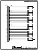
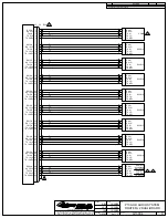
J3
D9M
10
COM1DIR
THIS DOCUMENT INCLUDES INFORMATION PROPRIETARY TO GENEVA
AVIATION AND SHALL NOT BE USED OR DUPLICATED BY ANYONE
WITHOUT THE WRITTEN PERMISSION OF GENEVA AVIATION, INC.
www.genevaaviation.com
SHT.
DATE
DATE
DATE
APPROVAL
PRO NO.
DRAWN
CHECKED
DWG NO.
TITLE
REV.
REVISION
DESCRIPTION
REV
APPROVAL
DATE
G13004
H
P139-HD AUDIO SYSTEM
G13115 CONTROL HEAD WIRING
GA182
13 of 13
RBH
10/30/08
JSW
10/30/08
CLB
10/30/08
J5
See sheet 1 for revision history
35
36
P3
D50M
5
J3
3
GND
6
COM ISO
P3
7
GND
8
TX PTT
9
ICS PTT
ICS KEY 1
XMIT KEY 1
P5 D15FS
TO CYCLIC PTT SWITCHES
Pilot Control Head
G13000 Digital Audio System
G13115 or G13116
12
Copilot Pin Assignment
NAME
G13115/6
G13000
COM2DIR
J3 pin 6
J5 pin 11
GND
J3 Pin 7
J5 pin 5
ICS KEY2
J3 pin 8
J4 pin 35
XMIT KEY 2
J3 Pin 9
J4 pin 36
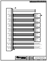
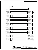
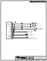
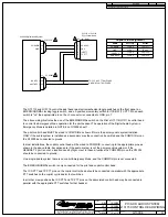
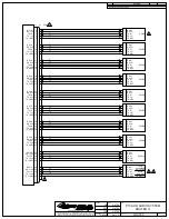
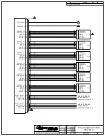
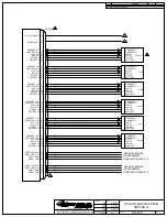
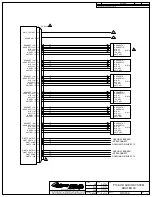
The G13115 and G13116 control heads thave two electromechanical toggle switches on the front panel; an
EMERG/NORMAL locking toggle switch, and a 3-position momentary switch for ICS/OFF/TX PTT. When each
switch is "on" the appropriate pin on the J3 connector is connected to GND, pin 7.
The above wiring illustrates the use of the EMER/NORMAL switch on the Pilot's G13116/G13116 control head
to control the Emergency Mode operation for the pilot headset. The operation of the Digital Audio System in
Emergency Mode is detailed in NOTE 8 on G13004 sheet 1.
The pilot control head MUST be wired to COM1DIR as shown if this is the primary audio system installed.
ONLY if the audio system is installed as a secondary may the connection be omitted and the COM1DIR pin on
the G13000 be connected to ground.
In most installations, the copilot control head will be wired to COM2DIR, connecting to the appropriate pins as
shown in the above table. Exceptions are if the audio system is not the primary audio system or if the
HEADSET 2 port is not at a location used by flight crew. In these situations the COM2DIR pin on the G13000
should be connected to ground.
On a single-board system there is no copilot Emergency Mode, and the COM2DIR pin is not connected.
The EMERG/NORMAL switch is only connected for the pilot and copilot control head.
The ICS PTT and TX PTT pins on the copilot control head should be connected in parallel with the appropriate
PTT switches on the copilot cyclic and/or foot switches.
In all other crew positions the ICS PTT and TX PTT pins on the associated control head may be connected in
parallel with the appropriate PTT switches for that headset.
AND/OR FOOT SWITCHES
Summary of Contents for P139-HD
Page 2: ......
Page 4: ......
Page 5: ......
Page 6: ......
Page 7: ......
Page 8: ......
Page 16: ......
Page 17: ......
Page 19: ......
Page 22: ......
Page 23: ......
Page 24: ......
Page 26: ......
Page 27: ......
Page 28: ......
Page 29: ......
Page 30: ......
Page 31: ......
Page 32: ......
Page 33: ......
Page 34: ......
Page 58: ......
Page 60: ......
Page 62: ......
Page 64: ......
Page 78: ......
Page 80: ......
Page 82: ......

