7001-MI-001
Revision --
Page 9 of 11
7.
System Testing
Failure to follow these instructions will result in improper operation.
7.1
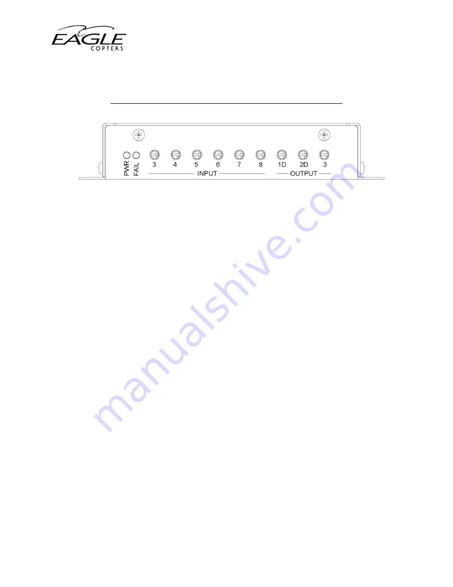
If the mixer is not powered or is in fault mode (Essential), Input 1 will be connected directly via
relay closure to Output 1D, and Input 2 will be connected directly to Output 2D. It is important
to follow the setup instructions exactly in order for the mixer to work properly in the Essential
Mode.
7.2
The mixer has internal fault detection. Upon fault, the relays go to their normally closed
(Failsafe) position and the FAIL indicator light will illuminate. Optionally, the installer may
connect Pin #10 (pull low) to an external fault indicator (see note #2 in Section 6.9). There are
no internal adjustments, jumpers or user serviceable parts. If the mixer fails, return it to Eagle
Copters USA, Inc. for repair or replacement.
7.3
The direct inputs in essential mode are non-adjustable. The level that is present at Inputs 1 and
2 will be present at 1D and 2D respectively.
7.4
Output 3 is not relay direct protected and therefore will drop off line in unpowered or fail mode.
This output is designed to be a monitor port to a non-critical device.
7.5
Before applying power, perform a continuity check of all leads to confirm they are connected
properly.
7.6
With the circuit breaker to the mixer pulled (Off) and the audio system on, adjust the source to
Audio Source 1D and 2D so that the proper level is heard at both the Pilot and Co-Pilots
Headsets when the source is triggered, i.e. Master Caution. DO NOT adjust the 1D or 2D outputs
of the mixer; instead, adjust the source to the mixer.
7.7
With all other avionics off, push the mixer's circuit breaker In (On). Verify visually that the power
indicator (PWR) is on, and the FAIL indicator is off. The mixer is now in powered mode. Trigger
the source for Inputs 1D and 2D. Adjust the mixer Output Adjustments 1D and 2D so that the
proper level is heard in the Pilot and Co-Pilot Headsets. It should be the same as in the
unpowered mode. Pull the circuit breaker to the mixer in order to verify this operation.
7.8
Once steps 7.6 and 7.7 are completed, turn on all avionics or other sources connected to Audio
Sources 3 through 8. Adjust the levels as required at Inputs 3 through 8 on the mixer. DO NOT
change the adjustments on Outputs 1D, 2D or 3.
7.9
After Completion of Steps 7.6 through 7.8, adjust Output 3 to the desired level required by the
device connected to Output 3.
Conduct EMI test in accordance with EMI Test Procedure 7001-TP-001.


