The material contained in this document is the property of Electronics & Innovation Ltd., it is
subject to change without notice.
August 2012
9
Revision E
Chapter 4 Maintenance
4.1 INTRODUCTION
The E&I A150 RF amplifier requires no periodic maintenance. The instrument is
unconditionally stable and is fail-safe under all load conditions. Damage can only
be externally caused by the incorrect selection of the AC supply voltage or by an
input signal in excess of the specified 1 volt rms equivalent to a power level of
13dBm.
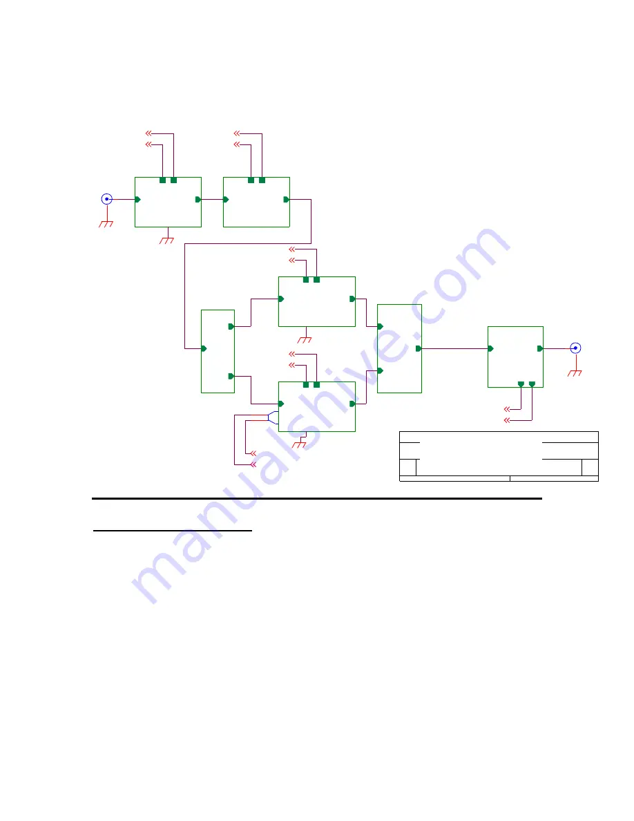
This chapter therefore, deals only with certain fundamental procedures for fault
location.
S1
VHF_splitter_20W
RF_in
RF_out1
RF_out2
50 ohm
+34dBm
+48V_ret
+48V_ret
+24V_ret
2100L-SCH-01
1
3200L - RF Section
A
2
1
Title
Size
Document Number
Rev
Date:
Sheet
of
C1
VHF_combiner_200W
RF_out
RF_in1
RF_in2
TS1
Thermal switch
1
2
IPA1_1
3W_VHF_amp
+
24V
RF_in
RF_out
Gnd
rev
+48V
J2
BNC
1
2
50 ohm
200W
IPA1_2
20W_VHF_amp
+
24V
RF_in
RF_out
Gnd
J6
+24V
PA1_2
VHF_PA_100W
+
48V
RF_driv e
RF_out
Gnd
J1
BNC
1
2
Front
panel RF
input
0dBm
CP1_1
VHF_coupler
RF_in
RF_out
F
w
d
R
ev
f wd
ov erheat
+48V
PA1_1
VHF_PA_100W
+
48V
RF_driv e
RF_out
Gnd
+24V
ov erheat_rtn
+24V_ret
A150 RF Amplifier
A150
– SCH-02


