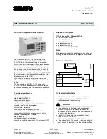
CREATED ON: May 18, 2017
Instruction Manual
S1DC8–M3
COMBINATION TIMER WITH 8 CHANNELS
EAPL
Introduction
On power application and shorting of S1 & S2 terminals, the timing starts,
each of the relays comes ON after the preset delay timing and remain
ON till the Preset ON timing. All 8 relays switches ON & OFF in different
combinations as per the program. After completion of all combinations
clock resets to zero and depending on the status of C1-C2, timer
continues to execute the same program or waits for fresh start signal. If
Run/Prog switch is slided from program mode to run mode, timer waits
for fresh start signal.
Box Accessories
One (1) S1DC8–M3COMBINATION TIMER WITH 8 CHANNELS
One (1) Instruction manual
Safety Precautions
Read and follow all the safety precautions and instructions before
installing and working with the equipment.
•
Shorting of C1-C2, S1-S2, and I1-I2 & R1-R2 shall be potential free;
applying power to these terminals will damage the timer permanently.
•
Timing not initiated.
•
S1- S2 signal shall be applied.
•
I1- I2 shall be open.-
!
DANGER
HAZARD OF ELECTRIC SHOCK, EXPLOSION OR ARC FLASH
•
Apply appropriate personal protective equipment(PPE) and follow
safety work practices
•
Only qualified electrical workers should install this equipment. Such work
should be performed only after reading this entire set of instructions.
•
If the equipment is not used in the manner specified by the
manufacturer, the protection provided by the equipment may be
impaired.
•
NEVER work alone.
•
The successful operation of this equipment depends upon proper
handling, installation and operation. Neglecting fundamental installation
requirements may lead to personal injury as well as damage to
electrical equipment or other property.
•
NEVER bypass external fusing.
Failure to follow these instructions will result in death or serious injury.
•
EAPL is not responsible for any consequential damages arising out of use
of our products, though the technology is cautiously chosen and
implemented like any other well designed good electric device.
Tools and Fasteners
Kindly use star – type screw driver for tightening the screws.
NOTE:
Installation should include a disconnecting device, like switch or
circuit breaker, with clear ON/OFF markings, to turn-off the auxiliary
supply (control power).The disconnecting device should be within the
reach of the equipment and the operator
.
Dimension
Note: All Dimensions are in mm.
Front Panel
Terminal Details
A1,A2 : Source
S1-S2 : Start signal for a minimum of 150mS.
C1-C2 : SHORT – Single cycle operation
(i.e. timer stops at the end of first cycle)
OPEN – Cyclic operation
(i.e. timer continues to operate).
I1-I2 : Time Pause Input. By shorting these terminals timing is
temporarily stopped and relay status is maintained,
again by opening timing continues.
R1– R2 : PROGRAM RESET:
After shorting these terminals slide PROG/RUN switch to
PROG mode. This will erase all previously programmed
On time & delay time settings.
HOLD MODE: Continue the timing after resumption of interrupted
power & balance time is executed.
RESTART MODE: After the resumption of interrupted power,
timer waits for fresh start signal.
Page 1 of 2
OD RS AN 210001 REV 01/18-05-17


