background image

INSTALLATION 
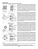
Combustible Wall Chimney Connector Pass-Throughs 


NOTES: 

1. 

Connectors to a masonry chimney, excepting method B, shall extend in one continuous section through the wall pass-through system 
and the chimney wall, to but not past the inner flue liner face. 

2. 

A chimney connector shall not pass through an attic or roof space, closet or similar concealed space, or a floor, or ceiling. 

3. 

Where passage through a wall, or partition of combustible construction is desired, the installation shall conform to CAN/CSA-B365. 

PAGE 12 


Method A. 12 inch (305 mm) Clearance to Combustible Wall Mem-
ber: Using a minimum thickness 3.5 inch (90 mm) brick and a 5/8 
inch (16 mm) minimum wall thickness clay liner, construct a wall 
pass-through.  The clay liner must conform to ASTM C315 (Stan-
dard Specification for Clay Fire Linings) or its equivalent. Keep a 
minimum of 12 inches (305 mm) of brick masonry between the 
clay liner and wall combustibles.  The clay liner shall run from the 
brick masonry outer surface to the inner surface of the chimney 
flue liner but not past the inner surface.  Firmly grout or cement 
the clay liner in place to the chimney flue liner.   
 
Method B. 9 inch (229 mm) Clearance to Combustible Wall Mem-
ber: Using a 6 inch (152 mm) inside diameter, listed, factory-built 
Solid-Pak chimney section with insulation of 1 inch (25.4 mm) or 
more, build a wall pass-through with a minimum 9 inch (229 mm) 
air space between the outer wall of the chimney length and wall 
combustibles.  Use sheet metal supports fastened securely to wall 
surfaces on all sides, to maintain the 9 inch (229 mm) air space.  
When fastening supports to chimney length, do not penetrate the 
chimney liner (the inside wall of the Solid-Pak chimney).  The in-
ner end of the Solid-Pak chimney section shall be flush with the 
inside of the masonry chimney flue, and sealed with a non-water 
soluble refractory cement.  Use this cement to also seal to the 
brick masonry penetration.  
 
Method C. 6 inch (152 mm) Clearance to Combustible Wall Mem-
ber: Starting with a minimum 24 gage (.024 inch [.61 mm]) 6-inch 
metal chimney connector, and a minimum 24 gage ventilated wall 
thimble which has two air channels of 1 inch (25.4 mm) each, con-
struct a wall pass-through. There shall be a minimum 6 inch (152 
mm) separation area containing fiber glass insulation, from the 
outer surface of the wall thimble to wall combustibles.  Support the 
wall thimble, and cover its opening with a 24-gage minimum sheet 
metal support. Maintain the 6 inch (152 mm) space.  There should 
also be a support sized to fit and hold the metal chimney connec-
tor. See that the supports are fastened securely to wall surfaces 
on all sides.  Make sure fasteners used to secure the metal chim-
ney connector do not penetrate chimney flue liner.   
 
Method D.  2 inch (51 mm) Clearance to Combustible Wall Mem-
ber:


Start with a solid-pak listed factory built chimney section at 

least 12 inches (305 mm) long, with insulation of 1 inch (25.4mm) 
or more, and an inside diameter of 8 inches (2 inches [51 mm] 
larger than the 6 inch [152 mm] chimney connector). Use this as a 
pass-through for a minimum 24-gage single wall steel chimney 
connector. Keep solid-pak section concentric with and spaced 1 
inch (25.4 mm) off the chimney connector by way of sheet metal 
support plates at both ends of chimney section.  Cover opening 
with and support chimney section on both sides with 24 gage 
minimum sheet metal supports. See that the supports are fas-
tened securely to wall surfaces on all sides. Make sure fasteners 
used to secure chimney section do not penetrate chimney flue 
liner. 

D

C

B

A

Summary of Contents for EARTHSTOVE 1500HT

Page 1: ...UAL RETAIN THESE INSTRUCTIONS FOR FUTURE REFERENCE THIS APPLIANCE MUST BE INSTALLED BY A QUALIFIED INSTALLER READ ENTIRE MANUAL THOROUGHLY BEFORE INSTALLATION P P N 775001M Rev Q 12 03 MODEL 1500HT EP...

Page 2: ...use gasoline gasoline type lantern fuel kerosene charcoal lighter fluid or similar liq uids to start or freshen up a fire in this heater Keep all such liquids well away from the heater while it is in...

Page 3: ...eeds reflects their concern for aesthetics efficiency and our environment We extend our continued support to help you achieve the maximum benefit and en joyment available from your new wood stove It i...

Page 4: ...ts in your area NOTE This appliance is NOT approved for installa tion into a Manufactured Mobile Home in Canada SELECTING A LOCATION The design of your home and where you place your stove will determi...

Page 5: ...rrestor Clearances inches millimeters A 10 267 C 15 381 E 9 241 B 20 508 D 8 203 F 5 127 CORNER INSTALLATION PARALLEL INSTALLATION ALCOVE CLEARANCE Required pipe Type L Vent pipe to top of stove Ap pr...

Page 6: ...air in a house that is well insulated OUTSIDE AIR In all manufactured mo bile homes and in many site built residences sub ject to local code a stove may be required to use outside air for combustion A...

Page 7: ...To do this simply attach a piece of No 8 copper wire at least 18 457 mm in length from the stove to the chassis of the manufactured mobile home Marble is a natural product and therefore each piece wil...

Page 8: ...be replaced Do not operate this appliance without the baffle brick properly installed TOP VIEW OF BAFFLE BRICK SIDE VIEW OF BAFFLE BRICK TYPES OF CHIMNEYS The chimney is a vital part of your stove ins...

Page 9: ...epartment for chimney code requirements A masonry chimney must have a code approved liner This liner must not have broken or missing pieces Some non code masonry chimneys may be brought up to code by...

Page 10: ...red flow of combustion air to the fire chamber and for safely removing unwanted combustion byproducts from the appliance If the venting system s design does not pro mote these ends the system may not...

Page 11: ...ON PAGE 11 RESIDENTIAL STANDARD Using 6 152 mm Diameter Single Wall Con nector Pipe Not Approved For Manufactured Mobile Home MANUFACTURED MOBILE HOME STANDARD Using 6 152 mm Diameter Type L Vent Conn...

Page 12: ...l of the Solid Pak chimney The in ner end of the Solid Pak chimney section shall be flush with the inside of the masonry chimney flue and sealed with a non water soluble refractory cement Use this cem...

Page 13: ...ed to try different settings so you can learn how much heat to ex pect and how long the fire will burn FUEL DOOR CAUTION WHEN OPENING THE DOOR DO NOT EX TEND IT BEYOND ITS NORMAL TRAVEL OVEREX TENDING...

Page 14: ...t least medium high or about 450 F for 45 60 minutes The paint will become soft and emit non toxic haze during these burns Keep the area well ventilated As the paint cures it will become slightly ligh...

Page 15: ...l seasoned natural wood What does Well Seasoned mean When a tree is cut down the wood is green full of sap and moisture This moisture content can exceed 80 which must be reduced to less than 20 Wood p...

Page 16: ...m all combustible materials pending final disposal If the ashes are disposed of by burial in soil or other wise locally dispersed they should be retained in the closed container until all cinders have...

Page 17: ...ue are more susceptible to creosote deposits To inhibit the build up of creosote adjust the primary air control to a medium high or high setting for a 10 minute period each day Do not attempt to burn...

Page 18: ...draw to sustain a high heat output rate DOES NOT MAINTAIN A FIRE 1 Soft wood does not burn as long or as well as seasoned hardwood resulting in a short burn time 2 Wood size too small Burns at too ra...

Page 19: ...used From Improper Operation Operate this appliance only as outlined in this manual Never burn the ap pliance with the fuel door or ash drawer open or ajar Do not operate this stove with the Air Contr...

Page 20: ...bs 16 kg Firebox Size 1 85 cubic feet 564 cubic mm Maximum Burn Rate BTU 58 730 EPA BTU Range 11 700 37 000 EPA Efficiency 63 Emissions Rate grams hour 6 6 gph Loading Front Approx weight with brick 3...

Page 21: ...aft 907 Module Coil Handle brass Component Parts 1100 Ash Drawer Assembly 1135 Knob Ash Drawer 27M80H Gasket Ash Drawer 3 8 wide X 1 8 thick 13009 Trim Top Louver Fan System Parts if optional kit s in...

Page 22: ...mensions FB 1 6 9 x 4 1 2 FB11 1 4 1 2 x 4 3 8 FB2 10 9 x 4 1 2 w notch 10545 5 9 x 4 1 2 w notch 01115 1 Grate FB 5 1 9 x 2 1 2 w hole Baffle brick are a special denser brick Do not substi tute Note...

Page 23: ...Kit 14M22 BK 100 Blower Kit Includes Dial A Temp for Variable Speed Control 14M21 SSK Stove Stat Kit Thermally Controls Blower 70K99 TSPK B Touch up Spray Paint Kit Black 12 oz Spray Can Outside Air F...

Page 24: ...SAFETY LISTING LABEL PAGE 24...

Page 25: ...EPA LABEL PAGE 25...

Page 26: ...26 OWNERSHIP RECORDS Dealer s Name Dealer s Address City State Zip Code Serial Number Date of Purchase Date Installed Notes SERVICE AND MAINTENANCE LOG Service Service Service Date Technician Descrip...

Page 27: ...1110 West Taft Avenue Orange CA 92865...

Reviews: