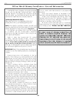
background image

18

Earthcore Industries

BVETTO B-Vent Gas Fireplace 

08/2017

Assembly Instructions - BVETTO B-Vent Series

9. 

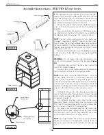
The high temp lintel, as supplied, is forty five inches (45”) 

long and fits the BVETTO models 36 & 46. Field cut the high 

temp lintel equally at the perforated lines as required for the 

36” unit. This will ensure the limit switch and micro-switch 

are located in the proper position on the lintel.

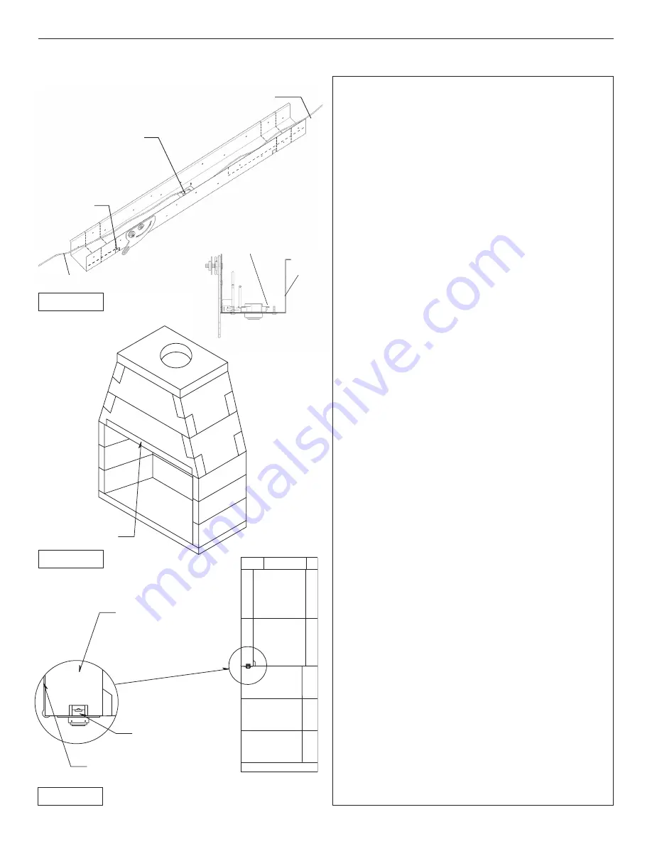
   Connect the two (2) leads from the high temperature 

wires to the thermocouple junction block (see diagram, 

page 29).


Measure and locate the centerline of the fireplace open-

ing. Align notch at the front of the lintel to the centerline of 

the fireplace. Install lintel using 1 1/2” masonry screws.

NOTE: 

The limit switch and microswitch are already sup-

plied and mounted in the BVETTO high temp lintel compo-

nent. Connect the two high temperature wires (coming out 

the top of the BVETTO left hand firebox side wall) to the two 

high temperature wires that are attached to the limit switch 

with ceramic wire nuts. 


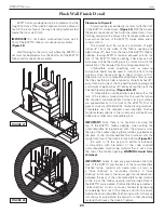
The small tab near damper lever should be bent upward 

to stand vertical. This protects wires passing through the 

harness.

WARNING:

 Do not bypass the high temperature limit 

switch.  Install downdraft diverter at the top plate. 

(Figure 

20)


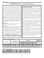
Orient assembly such that the wire cable is toward the 

front of the fireplace opening.


Loosen screws on the cable clamp and loop between 

the two washers at the end of the handle asembly.

NOTE:

 Wire clamp should be approximately 4” from the 

washers. Tighten lock nuts on the handle if necessary. Pull 

cable to close the damper and adjust the length of wire 

cable by swinging the handle between open and close po-

sitions. When in the open position, the damper should be 

rotated a full 90 degrees from the closed position. Retighten 

screws on the cable clamp and remove excess cable. 


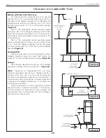
The high temp lintel fits horizontally up toward the bot-

tom of the smoke dome. The adjoining short leg of the high 

temp lintel fits up against the bottom  of  the smoke dome 

component. (Figure 19)


The high temp lintel has 4 pilot holes for the screw 

placement. Attach the high temp lintel flush against the 

front face of the smoke dome with 4 mounting screws driv-

en into the face of the BVETTO smoke dome.


Any excess wire draped between the high temp lintel 

and the left hand firebox sidewall should be neatly tucked 

into the hollow core of the left hand sidewall. Excess wire 

should not be visible below the canopy bottom.

NOTE: 

The 2 high temperature wires inside of the BVETTO 

firebox will connect to the appropriate contacts found on 

the gas log assembly during the installation of the gas log 

set.  

High Temperature

Limit Switch

2 High Temperature

Wires

Tab to be bent upward

to stand vertical
(both sides)

Front 
Facing

Limit Switch
Terminals

Smoke Dome
Component

Metal Canopy

High Temperature
Limit Switch

Metal Canopy

Smoke Dome
Component

Metal Canopy

High Temperature
Limit Switch

Metal Canopy

FIGURE 18

FIGURE 19

FIGURE 20

Alternate wire location

Summary of Contents for BVETTO 36 inch

Page 1: ...actly could result in serious injury death or property damage Do not store or use gasoline or other flammable vapors and liquids in the vicinity of this or any other appliance WHATTO DO IFYOU SMELL GA...

Page 2: ...D FUEL SUITABLE FOR USE WITH PROPANE LP OR NATURAL GAS SEE GAS IDENTIFYING TAG ON BURNER IBV36 MODEL 80B36 PROPANE LP BTU MIN 22 000 BTU MAX 50 000 IBV36 MODEL 80B36 NATURAL GAS NG BTU MIN 21 000 BTU...

Page 3: ...manual 4 Burning of anything solid fuel other than the listed gas log unit and the type of gas approved for use in this gas appliance The most important areas of concern with the installation of the...

Page 4: ...se with the type of gas indicated on the rating plate This appliance can be field converted for use with other gases with Propane LP or Natural Gas NG 4 Earthcore Industries BVETTO B Vent Gas Fireplac...

Page 5: ...sed when they are in the same room as the appliance Toddlers youngchildrenandothersmaybesusceptibletoaccidental contact burns A physical barrier is recommended if there are at risk individuals in the...

Page 6: ...36 80B36 22 71 31 27 10 43 36 8 High Temp Lintel 31 25 71 36 34 5 16 16 Down Draft Diverter 25 43 27 36 8 Front View Side View Plan View Top View 10 25 14 22 Flue Outlet Uses 10 Metal Fab or DuraVent...

Page 7: ...QTY 2 16 4 42 11 Isokern BVETTO Smoke Dome QTY 2 4 25 10 36S Isokern BVETTO Top Plate 25 Isokern BVETTO Backwall QTY 3 30 10 16 4 32 22 NOTE One additional backwall and two additional sidewalls can b...

Page 8: ...46 80B46 33 71 31 37 10 53 47 8 High Temp Lintel 31 25 71 36 34 5 16 16 Down Draft Diverter 25 53 37 47 8 Front View Side View Plan View Top View 10 25 14 33 Flue Outlet Note These are inside rough di...

Page 9: ...QTY 2 16 4 42 11 Isokern BVETTO Smoke Dome QTY 2 4 25 10 77 Isokern BVETTO Top Plate 31 Isokern BVETTO Backwall QTY 3 40 10 16 4 52 33 NOTE One additional backwall and two additional sidewalls can be...

Page 10: ...beyond the finished sides of the fireplace opening IMPORTANT Combustibles are defined as normal construction materials and considered to be wood framing materials particle board mill board plywood pan...

Page 11: ...rn unit model weights a BVETTO 46 1400 lb b BVETTO 36 1200 lb 2 Approximate weight of log set 100 lb 3 Fire brick and Adhesive 350 lbs 1800 lbs depending on brick size and pattern 4 Facing material pe...

Page 12: ...0 required clearance at the sides of the Fireplace 4 Rough framing dimension for depth C allows for the required 1 1 2 clearance at the back of the Fireplace 5 Opening height of 83 requires minimum 9...

Page 13: ...as a sign of complete and proper sealing of the joint On broader contact surfaces it is advisable to apply several additional 1 2 beads of the Earthcore Adhesive to the area to assure proper sealing...

Page 14: ...fireplace elevated above the room s floor then the base plate can be set on a noncombustible platform that is built up to the desired raised hearth height on the concrete support slab Figure 11 When c...

Page 15: ...ETTO base plate Figure 14 This drill hole must intersect the hollow core of the BVETTO firebox side wall Feed the two lengths of high temperature wire from the inside of the BVETTO firebox through the...

Page 16: ...ebox for level If necessary adjust the top surface of the box assembly for level by inserting a shim supplied with the unit between the lowest wall component and the top surface of the base plate Any...

Page 17: ...moke dome components that are already in place Set the two upper smoke dome sloping sidewalls into position one at each end of the upper front and rear smoke dome components Figure 17 8 Set the top pl...

Page 18: ...hers at the end of the handle asembly NOTE Wire clamp should be approximately 4 from the washers Tighten lock nuts on the handle if necessary Pull cable to close the damper and adjust the length of wi...

Page 19: ...rface of the chimney could be contacted by persons or combustible materials The air space between the outer wall of the chimney and the enclosure shall not be less than 1 inches Except for installatio...

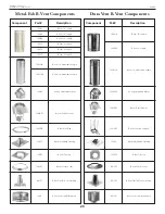
Page 20: ...le Elbow 10MF B Vent Standard Flashing 10MFT B Vent Flat Tall Cone Flashing 10MSC B Vent Storm Collar 10MFS B Vent Firestop 10MC B Vent Vent Cap Termination 10MGR B Vent Guy Ring 10MDD1 B Vent Draft D...

Page 21: ...e lintel hook should be mounted in a position so as to provide a small amount of tension in the spring attached to the chain The tension is needed to prevent the damper plate from rattling when closed...

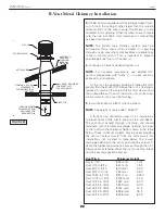
Page 22: ...Vent Cap should be used on all installations to prevent back drafts and to keep out rain and debris The vent must extend through a flashing and should terminate with the lowest discharge opening no cl...

Page 23: ...2 Dip each firebrick in a pale of water before applying mortar to one side for adherence to firebox 2 Face joint dimensions of 1 8 to 3 8 in the brick work is recommended and has the best appearance O...

Page 24: ...inimum of eight inches 8 inches above the top of the finished fireplace opening Figure 26 27 If combustible wood sheathing is installed across the face of the Isokern smoke dome front be sure that whe...

Page 25: ...inches 24 to the finished fireplace opening Figure 35 Ceilings The minimum clearance from the top of the fireplace opening to a ceiling is forty two inches 42 Figure 34 NOTE Clearance to Combustible T...

Page 26: ...minimum inlet gas supply pressure for purposes of input adjustment is 5 water column w c on natural gas and 11 w c on L P gas Insuffi cient gas pressure will affect proper operation of the pilot if eq...

Page 27: ...tion Part No Qty Part No Qty 1 or Pilot assembly natural Pilot assembly propane PAC 12 PAC 12P 1 1 PAC 12 PAC 12P 1 1 2 or Control valve natural Control valve propane SV 47 SV 47P 1 1 SV 47 SV 47P 1 1...

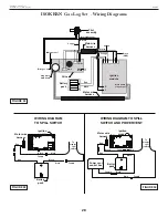
Page 28: ...motor main flame Main gas out Pilot gas out Main flame step output Copper Black GND Pilot Pilot assembly WIRING DIAGRAM TO SPILL SWITCH WIRING DIAGRAMTO SPILL SWITCH AND POWERVENT Ignition module Mot...

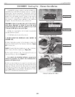
Page 29: ...FIREPLACE GAS SUPPLY IS TURNED OFF 2 Place the burner system in the fireplace Center the burner from left to right in the fireplace Reference Figure 35 for orientation NOTE Ensure the porcelainized pa...

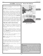
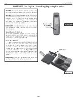
Page 30: ...fireplace It should rest with its bottom as near as possible and facing the fireplace wall It must not be placed directly next to the burner pan area to avoid damage to the batteries See Figure 41 Fi...

Page 31: ...The lava granules may be placed around the switch box Leave the front of the switch box clear for control access 14 Repeat this process for the supplied lava coals on top of the already placed lava gr...

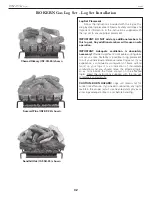
Page 32: ...eable sooting does not occur some flexibility is possible in log placement to suit your individual preference select log sets If you experience a continued accumulation of black carbon soot on your lo...

Page 33: ...ansmitter remove the lid found on rear and properly insert the new battery as marked Re secure the lid Figure 46 Switch Box Batteries The burner system requires 4 AA batteries to operate included Loca...

Page 34: ...e pilot by hand NOTE If the remote does not function and batteries with an adequate power level are installed refer to the SYNCING THE REMOTE section NOTE Steps 1 and 2 may not be required if previous...

Page 35: ...hnician NOTE In manual mode the remote transmitter will not operate the burner system Shutting Down For remote shut down press the OFF button on the remote transmitter If remote is unavailable slide t...

Page 36: ...is on this button is used to increase the flame to the desired height LOW BUTTON When the system is on this button is used to decrease the flame to the desired height FLAME HEIGHT Seven flame height l...

Page 37: ...e warning tags These are an integral safety and identification component of this appliance We recommend following these instructions at the beginning of each fireplace season and as needed throughout...

Page 38: ...ion 1 A1 of this table BURNER NOT BURNING EVENLY A Burner orifice clogged A Clean burner orifice B Remote set on low fl ame if option available B Adjust flame with remote transmitter C Top burner ligh...

Page 39: ...l The ADC100 Control for gas appliances has pre and postpurge features an integrated damper relay and includes a draft switch that shuts the appliance off when there isn t enough draft protecting your...

Page 40: ...damper operation and the safety system No adjustments are necessary after the system is installed and commissioned The ADC100 does not have to be visible and can be installed in the attic Figure 57 P...

Page 41: ...MEANS AND CIRCUIT PROTECTION ARE TO BE PROVIDED BY THE INSTALLER OF THIS DEVICE 1 All wiring must be in flexible or rigid metal conduit LEGEND 24 VAC 120 VAC N L FAN CONTROL UNIT 7 8 9 10 11 12 13 14...

Page 42: ...________________________ _________________________________________ 42 Earthcore Industries BVETTO B Vent Gas Fireplace 08 2017 Notes _________________________________________ _________________________...

Page 43: ...80B36 BVETTO 46 80B46 Gas Type Circle One Natural Gas Propane Fireplace Serial Number ________________________________________________________________________________ Located on Rating Plate Inside F...

Page 44: ...on If a component is found to be defective under the terms of this warranty the party to whom this warranty is extended shall notify Earthcore 6899 Phillips Industrial Blvd Jacksonville Florida 32256...

Reviews: