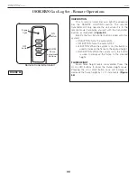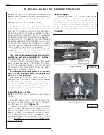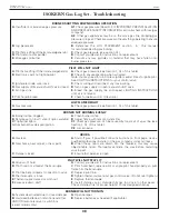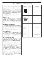
41
Earthcore Industries
08/2017
BVETTO B-Vent Gas Fireplace
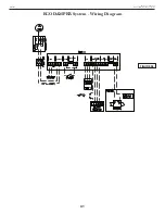
ECODAMPER System - Wiring Diagram
MECHANICAL DRAFT SYSTEM FOR A GAS-
FIRED FIREPLACE WITH DAMPER AND
SAFETY SYSTEM PER NFPA 54/IFGC
APPLICATION
This installation shows a combination fireplace and
damper system. The ADC100 control monitors fan and
damper operation and the safety system. No adjust-
ments are necessary after the system is installed and
commissioned. The ADC100 does not have to be vis-
ible and can be installed in the attic.
Proven Draft Switch is part of ADC100 control.
SEQUENCE OF OPERATION
1. During commissioning, the fan speed is set using
the potentiometer located on the ADC100
control board.
2. When the gas igniter is activated, the fan speed
increases and the damper begins to open. Once
the damper is fully open and the proven draft
switch closes, the fan returns to the speed setting
of the potentiometer and the ADC100 releases
the gas valve.
3. If proper draft is not maintained, the ADC100 will
increase fan speed gradually until the PDS closes.
If the PDS has not closed 10 seconds after the
fan reaches 100% speed, the ADC100 will shut
off the gas valve and go into alarm mode. If
the PDS closes while in alarm mode, the fan will
resume the original speed setting.
4. Once the fireplace is turned off, the fan will
continue to operate for a set post-purge time
(adjustable between 0-10 minutes) to remove any
remaining products of combustion before shutting
down. The damper closes 10 seconds after the
fan is shut off.
5. In case of a mechanical or electrical failure the
ADC100 will shut off the gas valve.
RED
ORANGE
WHIT
E
BLAC
K
GREEN
FAN
MOTOR
120/1/60
NOTES:
THE DISCONNECT MEANS AND CIRCUIT PROTECTION ARE TO
BE PROVIDED BY THE INSTALLER OF THIS DEVICE
1
All wiring must be in
flexible or rigid metal
conduit
LEGEND:
24 VAC
120 VAC
N
L
FAN CONTROL UNIT
7 8 9 10 1
1 12 13 14 15 16 17 18 19
1 2 3 4 5 6
WEATHERPROOF BOX
MAIN CONTROL UNI
T
6 5 4 3 2 1
All wiring must be in
metal conduit or
shielded cable
Note:
The diagram is for
reference only. Job specific
wiring diagrams can be
provided by ENERVEX.
FIGURE 58

