Earthcore Industries
Isokern Maximus Linear Series See-Thru Gas Fireplace
02/2021
44
Enervex ADC 100 INSTALLATION
ADC 100 Terminal Designation
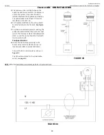
The designations for each terminal on the control board are shown below. Note that
Figure 45
only shows the terminals
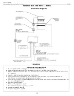
relevant to the Maximus Linear installation. Also shown in this section is a general connection diagram for an ADC100 control
system.
Terminal
Description
Terminal
Description
1
Line Power – L1
11
Proven Draft Switch NO; white
2
Line Neutral
12
Proven Draft Switch NC; gray
3
Ground
13
Proven Draft Switch C; purple
4
Fan Power to FSC
14
Line Power – L1 from junction box
5
Fan Neutral
15
Damper Power cord L
6
Fan Ground
16
Damper – actuator cord S1 NC; purple
7
Wall Switch
17
Damper – actuator cord S3 NO; white
8
Jumper to terminal 10
22
Terminal X4 on Proflame Module
9
Wall switch
23
Terminal X4 on Proflame Module
10
Jumper to terminal 8
NOTE
Damper power cord N must connect to junction box
neutral
FIGURE 45

