Earthcore Industries
02/2021
Isokern Maximus Linear Series See-Thru Gas Fireplace
57
Burner Installation
1.
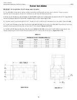
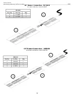
Connect all burner segments according to burner model diagram Page 58-60. Make sure all connections are tightly
secured.
2.
Place burner assembly in center of fireplace floor/cavity.
3.
Rotate the burner to position the gas inlet flared fitting to be on same side as the gas-supply stub coming from the gas valve.
(Not necessary for models ISF72/96LB)
4.
Remove the burner top closest to the gas-supply stub. Remove the top pan by unscrewing the two screws. This
will allow easier access and connection of flex connector to the flared fitting. This will also be used for pilot
assembly installation.
5.
Ensure the appropriate 3/8” flared fitting is connected to the gas supply stub.
6.
Connect the 12” flex connector to the gas inlet flared fitting on the burner assembly.
7.
Connect the other end of 12” flex connector to the gas-supply.
8.
Avoid creating kinks in the flex connector.
9.
Make sure all connections are tightly secured.
10.
Before replacing the removed burner top from
step 4
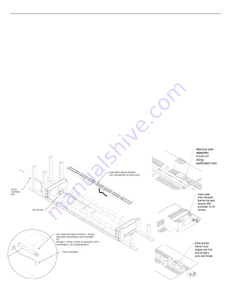
, locate the perforated rectangular section in the pan. Gently
remove this section along the perforations using a screwdriver or pliers.
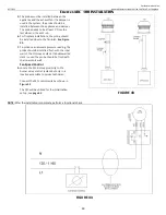
Figure 59
11.
Insert the pilot assembly from underneath the existing burner pan to the area of the removed burner section.
Figure 60
12.
Mount the pilot assembly to the removed burner pan using the screws provided with the pilot assembly. Be careful
not to kink the pilot assembly tube as it can severely damage the pilot tube.
Figure 61
13.
Place the removed burner top back on to the orifice block and secure tightly with the pan head screws.
14.
With gas line installed, complete burner lighting instructions on
page 61
and full system initialization on page 64
FIGURE 58
FIGURE 61
FIGURE 59
FIGURE 60

