Operator’s Manual
BADGER Front Tine Tiller
11
For additional information visit online at www.getearthquake.com or call 800-345-6007 M-F 8-5 CST
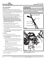
7. a. Assemble the upper handle bar assembly onto the lower
loop mount using four M8 bolts, four M8 flat washers
and four M8 locknuts. The handlebar as well as the bolt
should go on the outer side of the lower loop mount, while
the washer and nut should be placed on the inside. SEE
FIGURES 7 & 8
b. The upper two bolts can be assembled through one of
three hole positions depending on the user’s preferred
handle bar height (low, middle, high). For the highest height,
insert bolt into the most forward hole. For the lowest height,
insert bolt into the most rear hole. SEE FIGURE 7
8. Insert depth regulator/drag stake through bottom opening
in lower tail mount and secure with lock pin. SEE FIGURE 9
FIGURE 4
Dirt
Shield
Tine Shield
Engine
Mount Deck
High
Position
Medium
Position
Low
Position
Upper Bolt
Lower Bolt
Lower Loop Mount
FIGURE 7
FIGURE 3
Lower Tail
Mount
Washer
Wheel
Hairpin
FIGURE 5
FIGURE 6
Narrow
Tine
Width
Wide Tine
Width
Nylock
Nut
FIGURE 8
Drag Stake
FIGURE 9
Lock
Pin


