background image

Check for parts online at 

www.getearthquake.com

 or call 800-345-6007 M-F 8-5

14

Operator's Manual

VECTOR

 Compact Tiller

MAINTENANCE AND STORAGE

Your rototiller has been designed and produced by the 

industry’s leading manufacturer of outdoor power equipment 

to provide you with years of reliable operation. 
Please read the maintenance schedule in this manual for the 

tiller, and the maintenance schedule and recommendations 

in the accompanying engine manual.  Observe these 

recommendations to extend the life of your product.
Good maintenance is essential for safe, economical, and 

trouble-free operation. Keeping your tiller in top running 

condition will prolong its life, and help you obtain optimum 

performance.  It will also help reduce air pollution.  To help 

you properly care for your engine, the following pages include 

a maintenance schedule, routine inspection procedures, and 

simple maintenance procedures using basic hand tools. Other 

service tasks that are more difficult, or require special tools, are 

best handled by professionals and are normally performed by 

a technician or other qualified mechanic.  

Maintenance, replacement or repair of the emissions control 

devices and systems may be performed by any non-road 

engine repair establishment or individuals. However, items 

must be serviced by an authorized dealer to obtain “no charge” 

emissions control warranty service.  

The maintenance schedule applies to normal operating 

conditions. If you operate your tiller under unusual conditions, 

such as sustained high-load or high-temperature operation, 

or use in unusually wet or dusty conditions, consult your 

servicing dealer for recommendations applicable to your 

individual needs and use. 

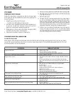
Maintenance 

Operation

Page

Before  

Each Use

50 hours or  

Every Season

Check belt tension

11

X

Change drive belt

14

X

Engine maintenance

15,

EM

X

X

Check or fill engine 

crankcase

15,

EM

X

1

Clean tine axle shaft

15

X

Lubrication

15

X

EM

 = See engine manual

1

 Change oil after first 5-8 hours of use, then after every 50 hours or 

every season. Change oil every 25 hours when operating under heavy 

load or in high temperatures.

MAINTENANCE SCHEDULE

Additional engine operation and related precautions and 

procedures can be found in the engine manufacturer’s manual 

that accompanies each tiller.

COLD STARTS

1.  Turn the On/Off switch to the 

ON

 position 

2.  Move choke lever to 

FULL CHOKE

 position.  

3.  Move throttle lever to half way between the 

SLOW


position and the 

FAST

 position.

4.  Pull starting rope out slowly one time and allow to return 

normally.

5.  Pull starting rope out rapidly, and allow rope to return 

normally. Repeat until engine starts.

6.  When engine starts, gradually move choke lever to run 

position and increase throttle speed to the 

FAST

 position 

for tilling.

Restarting A Warm Engine

Restarting an engine that is already warm from previous 

running does not normally require use of the choke.

1.  Turn the On/Off switch to the 

ON

 position.

2.  Move throttle lever to half way between 

SLOW

 and 

FAST

.

3.  Pull starting rope out rapidly until engine starts. Allow 

rope to return normally. Repeat until engine starts.

4.  Adjust throttle speed to the 

FAST

 position for tilling.

Operating Speed

For normal tilling, set the throttle lever to

 FAST

.

Shutting Down

To stop the engine at any time, turn the On/Off switch to the 

OFF position.  To stop tines at any time, release the drive safety 

control lever to the neutral position.

Tilling

1.  Adjust the depth regulator lever to desired tilling depth.

NOTE:  Raise depth regulator lever up one hole at a time, 

testing tiller operation after each raise. Raising 

depth regulator lever too high can result in loss of 

control of tiller!

2.  Move the throttle control to 

FAST

.

3.  Place the tiller in motion by pushing down on the drive safety 

control lever--this will engage the tines.

Summary of Contents for VECTOR

Page 1: ...nual Original Operating Instructions VECTOR Compact Tiller P N 13278 ECN 10647 REV8 11 01 14 2014 Ardisam Inc All Rights Reserved Get parts online at www getearthquake com GAS OIL RATIO 50 1 Product s 26750 14318 CE ...

Page 2: ...all applicable regulations of the U S Environmental Protection Agency EPA This manual may contain information for several models Read and keep this manual for future reference This manual contains important information on SAFETY ASSEMBLY OPERATION AND MAINTENANCE The owner must be certain that all the product information is included with the unit This information includes the MANUAL the REPLACEMEN...

Page 3: ...esult in serious injury or death Operate the machine according to the safety instructions outlined here and inserted throughout the text Anyone who uses this machine must read the instructions and be familiar with the controls Intended Use Foreseeable Misuse IMPORTANT This is a motorized rotary cultivator that works the soil by means of rotating tines It is pedestrian controlled but not self prope...

Page 4: ...the manufacturer Operate only in daylight or good artificial light Do not operate product when fatigued or under the influence of alcohol drugs or other medication which can cause drowsiness or affect your ability to operate this machine safely Never operate machine in wet grass Always be sure of your footing keep a firm hold on the handle and walk never run Watch for traffic when operating machin...

Page 5: ...osed on one or more sides under tents car ports or basements Always run the engine with the exhaust and muffler pointed in the direction away from the operator Never point the exhaust muffler towards anyone People should always be many feet away from the operation of the engine and its attachments Do not change the engine governor settings or over speed the engine Gasoline Fires and Handling Fuel ...

Page 6: ...re of a responsible adult Be alert and turn machine off if children enter the area Before and while moving backwards look behind and down for small children Never allow children to operate the machine Use extra care when approaching blind corners shrubs trees or other objects that may obscure vision Service Always stop the engine whenever you leave the equipment before cleaning repairing or inspec...

Page 7: ...ls now If you have any questions regarding their meaning or how to comply with these instructions reread the complete safety instruction text on the preceding pages For additional questions European customers may contact their local dealer and US customers must call Earthquake customer service Should any of the safety labels become unreadable because of being worn faded or otherwise damaged during...

Page 8: ...ction At All Times H Do Not Service or Adjust Moving Parts Unless Engine is Stopped and Spark Plug Wire is Disconnected I Dress Appropriately And Wear Sturdy Footwear J Toxic Fumes Do Not Operate in Unventilated Areas K Hot Surfaces L Fire Hazards M Do Not Use In Thunderstorms For severe weather stop operation of this machine and seek shelter N Team Lift For your safety always have at least two pe...

Page 9: ...0 rpm Europe WHEEL SIZE 8 diameter WEIGHT OF UNIT 90 lb UNIT SIZE L x W x H inches 51 x 24 x 41 SPECIFICATIONS Model 2006 42 EC Operator Ear LPA dBA 2006 42 EC Sound Power Level LWA dBA 2006 42 EC Hand Arm Vibration Max m s2 14318 CE 81 93 3 9 Sound and Vibration Levels DRIVE SAFETY CONTROL LEVER ADJUSTABLE FORWARD CONTROL CABLE ADJUSTABLE HANDLEBAR HEIGHT ADJUSTABLE DEPTH REGULATOR TRANSPORT WHEE...

Page 10: ... 2mm 6 Nuts M8 x 1 25 2 Middle Handlebar Straps 2 Hand Knobs 6 Bolts M6 x 1 0 x 12 6 Nylock Nuts M6 x 1 0 3 Remove machine from carton 4 Assemble the upper handlebar onto the lower handlebar loop as follows SEE FIGURES 1 AND 2 a Use the two 2 middle handlebar straps to connect the upper handlebar to the lower handlebar loop b Install the M8 x 25 bolts through the six lower bolt holes from the outs...

Page 11: ...r tines using the 8mm x 40mm lock pins already affixed to the inner tines Lock pins must be installed so that the pin enters the hole in the tine from the front of the tiller and so the wire bale hinges over the top of the tine pipe and latches to the protruding pin on the back side of the tine SEE FIGURE 5 Fill Engine Crankcase 1 Add oil according to engine manual Do not overfill Use a clean high...

Page 12: ...be replaced Drag Stake Tilling depth is controlled by the height of the drag stake depth regulator lever SEE FIGURE 8 To adjust tilling depth do as follows 1 Remove lock pin 2 Raise the depth regulator lever to position tines at chosen tilling depth Lowering the depth regulator will allow for deeper tilling 3 Align hole in depth regulator lever with hole in depth regulator bracket and replace lock...

Page 13: ... HOW TO USE THE TILLER PROPERLY KEEP CONTROL AT ALL TIMES STOP THE TINES AND WHEELS FROM TURNING AND STOP THE ENGINE IF NECESSARY IF YOU DO NOT KNOW HOW TO DO THESE THINGS READ THE CONTROLS AND SAFETY SECTIONS BEFORE PROCEEDING ALWAYS MAINTAIN CONTROL OF YOUR TILLER ONLY OPERATETILLER IN SOIL CONDITIONSTHAT ARE CONDUCIVE TO MAINTAINING CONTROL OF THE TILLER DO NOT OPERATE TILLER IN CONDITIONS THAT...

Page 14: ...ve belt 14 X Engine maintenance 15 EM X X Check or fill engine crankcase 15 EM X 1 Clean tine axle shaft 15 X Lubrication 15 X EM See engine manual 1 Change oil after first 5 8 hours of use then after every 50 hours or every season Change oil every 25 hours when operating under heavy load or in high temperatures MAINTENANCE SCHEDULE Additional engine operation and related precautions and procedure...

Page 15: ... Belt as follows 1 Turn off engine Engine must be cool 2 Remove spark plug wire from spark plug and secure 3 Remove top and lower belt guards 18129 and 18123 SEE FIGURE 10 4 Remove the belt from the engine pulley as follows a Gently pull the engine recoil rope to rotate the pulley b With the pulley turning force the belt out of the groove and slide the belt free of the engine pulley CAUTION CHECK ...

Page 16: ...ng a 30 weight oil WARNING PRACTICE SAFETY AT ALL TIMES ENGINE MUST BE TURNED OFF AND ALLOWED TO COOL AND SPARK PLUG WIRE MUST BE DISCONNECTED AND SECURED BEFORE ATTEMPTING ANY MAINTENANCE OR REPAIR FAILURETOCOMPLYWITHTHISSAFETYREQUIREMENT CAN RESULT IN SERIOUS PERSONAL INJURY TO YOU OR BYSTANDERS DO NOT STORE TILLER IN AN UNVENTILATED AREA WHERE FUEL FUMES MAY REACH FLAME SPARKS PILOT LIGHTS OR A...

Page 17: ...k plug Drive safety control lever must be released to neutral to start the engine Engine misses or lacks power Raise the tines for shallower tilling by raising the depth regulator lever Clean or replace air cleaner Improper carburetor adjustment take to authorized engine service center Replace spark plug and adjust gap Drain and refill gas tank and carburetor Tiller moves forward during starting D...

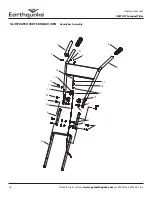
Page 18: ...ts online at www getearthquake com or call 800 345 6007 M F 8 5 18 Operator s Manual VECTOR CompactTiller ILLUSTRATED PARTS BREAKDOWN Handlebar Assembly 6 5 21 8 7 9 18 10 12 11 13 22 1 14 4 20 1 3 2 3 2 19 15 16 17 ...

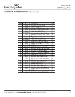
Page 19: ...7 53650 LEVER CONTROL 1 8 3248 NUT M5 X 0 8 HFNYLK 1 9 13159 BOLT 60D X 32 SHLDR M5 X 7MM HH 1 10 53629 BRACKET CABLE MOUNT 1 11 504 LOCKWASHER SPRING 5 16 1 12 12770 BOLT M8 X 1 25 X 40MM HH 1 13 13508 NUT M8 1 0 HSF 1 14 13822 CABLE FT PULLEY 787MM SHEATH 2 15 4620 NUT M8 X 1 25 HJAM 1 16 53620 SPRING COMPRESSION FORWARD ARM 1 17 IN58 NUT 5M X 0 8 NYLOC 1 18 11397 LINK 260MM LONG 1 19 13601 KNOB...

Page 20: ...etearthquake com or call 800 345 6007 M F 8 5 20 Operator s Manual VECTOR CompactTiller ILLUSTRATED PARTS BREAKDOWN Engine Assembly 26 27 25 27 26 21 22 9 30 17 18 19 20 15 5 6 7 4 1 11 11 24 8 2 23 13 14 12 16 3 28 10 10 10 29 11 31 ...

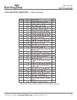
Page 21: ...IN CLEVIS 1 14 1418 PIN COTTER 1 15 18015 WELDMENT CABLE GUIDE PLATE 1 16 1407 SPRING FORWARD ARM 1 17 18043 SHIM 25 IN ENGINE MOUNT 2 18 3245 WASHER M8 8 4MM X 24MM X 2 2MM 4 19 W1200114 WASHER M8 X 1 9 SPRLK BLK OX HIGH COLLAR 4 20 18134 BOLT M8 X 1 0 X 35 GR8 8 ZN 4 21 18036 BELT V POWER RATED 861 MM 1 22 18022 PULLEY SINGLE GROOVE 16MM ID 1 23 739 BELT GUIDE REVERSE 1 24 13276 ENGINE VIPER 99C...

Page 22: ...e at www getearthquake com or call 800 345 6007 M F 8 5 22 Operator s Manual VECTOR CompactTiller ILLUSTRATED PARTS BREAKDOWN Chassis Assembly 5 9 8 11 16 12 15 3 8 11 14 22 23 17 7 6 2 13 13 11 1 10 7 4 8 20 21 8 18 21 19 ...

Page 23: ...1 25 X 45 HHFCS GR8 8 ZN 2 10 400024 WASHER FLAT M8 8 4 X 16 X 1 6 THK GR8 8 ZN 2 11 W1200117 WASHER M6 X 13 X 1 75 FLAT ZN 6 12 18123 WELDMENT GUARD PULLEY LOWER 1 13 18103 BOLT M6 X 1 0 X 40 HH GR 8 8 ZN 4 14 331052 NUT M12 X 1 75 HH NYLCK GR8 8 ZN 2 15 W1200116 WASHER M6 X 1 5 SPRLCK ZN 2 16 18119 WELDMENT SHIELD TINE MIDDLE 1 17 10513 BOLT M12 X 1 5 X 96 HH SHLDR M15 7 X 42 2 18 18118 WELDMENT...

Page 24: ...hquake com or call 800 345 6007 M F 8 5 24 Operator s Manual VECTOR CompactTiller ILLUSTRATED PARTS BREAKDOWN Transmission Assembly 20 22 24 27 9 8 26 25 23 6 14 28 4 16 15 28 14 6 13 11 10 18 3 19 2 15 17 1 5 26 7 12 27 29 24 22 21 23 25 ...

Page 25: ...OLT M8 X 1 25 X 20 HHCS ZN 1 14 13902 BEARING BALL 25MM ID 2 15 3220 BEARING TAPERED ROLLING 30204 20 X 47 X 15 2 2 16 13615 GEAR BRASS 25MM ID 6MM KEY FT 1 17 13590 BUSHING 26MM X 20 22MM X 6 6MM 1 18 13619 PULLEY TRANS SINGLE GROVE 1 19 3309 BEARING 6004 2RS 1 20 13905 TINE SET OUTSIDE RIGHT FT 25MM SHAFT 1 21 13904 TINE SET OUTSIDE LEFT 25MM SHAFT 1 22 13903 TINE SET INSIDE LEFT OR RIGHT 25MM S...

Page 26: ...eration accident acts of God or other events beyond Ardisam s control vandalism unauthorized parts failure to use proper fuel and oil or if repairs have been performed at a non authorized service facility These warranties shall not cover damage from normal wear and tear normal maintenance parts and services lightning nor improper installation operation storage or maintenance nor operating the equi...

Page 27: ...Check for parts online at www getearthquake com or call 800 345 6007 M F 8 5 27 Operator s Manual VECTOR CompactTiller ...

Page 28: ...nue PO Box 666 Cumberland WI 54829 800 345 6007 Fax 715 822 2223 E mail info getearthquake com All weights specifications and features are approximate and are subject to change without notice Due to continuous product improvements product images may not be exact Items used for props not included Some assembly may be required ...

Reviews: