Operator's Manual
Trail Warrior Quick Split 12-Ton Log Splitters
Check for parts online at www.getearthquake.com or call 800-345-6007 M-F 8-5
15
(European Version) Slide ram assembly, including flow
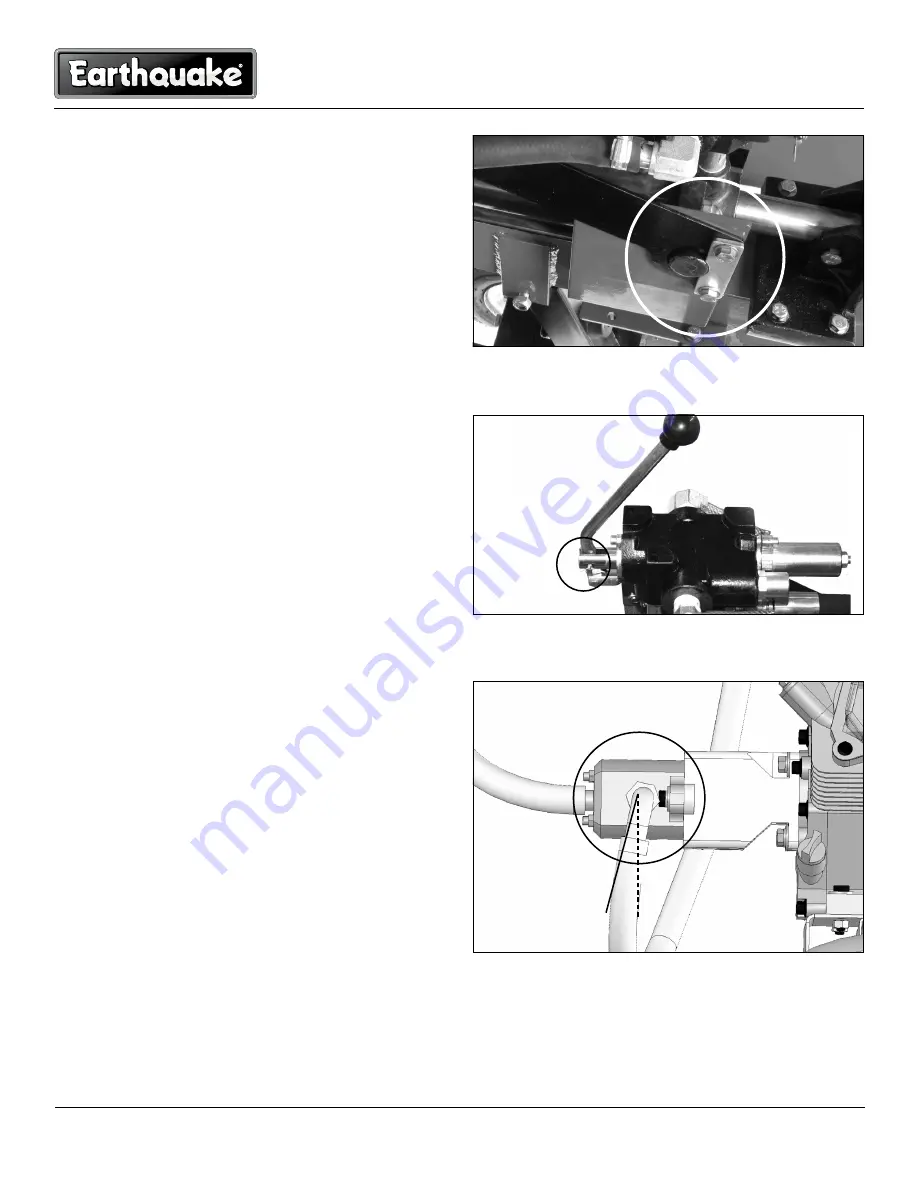
valve mount support, to rear bracket and attach with (4)
20mm bolts, lock nuts, and (2) retainer plates. SEE FIGURE
9.
8. (U.S. Version) Install hydraulic valve control lever. Secure
with pin and cotter key. SEE FIGURE 10.
(European Version) Install both hydraulic valve control le-
vers. Secure with pin and cotter key. SEE FIGURE 10.
9. (U.S. Version) Install high pressure hydraulic hose to pump/
engine assembly and hydraulic valve assembly. Swivel end
of hose goes on pump. SEE FIGURE 14.
Notice the approximate 12 o'clock position of hydraulic
fitting. SEE FIGURE 15.
TIp: Jiggle the fitting while tightening to ensure proper
seating of the fitting.
(European Version) Install high pressure hydraulic hose to
pump (port 2P) and flow control valve (port 2B) if not al-
ready attached. SEE FIGURE 12 aND 13.
Notice the approximate downward 7 o’clock position of
hydraulic fitting. SEE FIGURE 11.
Tip: Jiggle the fitting while tightening to ensure proper
seating of the fitting.
10. (U.S. Version) Install hydraulic supply hose on pump and
tank assembly. Slide hose onto hose barb until snug and
tighten with hose clamp. SEE FIGURES 15 aND 16.
(European Version) Install hydraulic supply hose on pump
(port 1P) and tank (port 1T) if not already attached. Slide
hose onto hose barb until snug and tighten with hose
clamps. SEE FIGURE 12 aND 13.
11. (European Version) Install return hose on tank (port 2T)
and on Elbow fitting/T-fitting assembly attached to flow
valve (port 1B) if not already attached. Slide hose onto hose
barb until snug and tighten with hose clamps. SEE FIGURE
12 aND 13.
12. (European Version) Install log cradle onto tank beam using
(2) 90mm bolts, (2) 5/16-24 bolts, and (4) nylock nuts. SEE
FIGURE 17.
13. See Hydraulic Filling instructions.
Figure 9
Figure 10
Figure 11


