Page 7
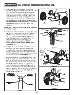
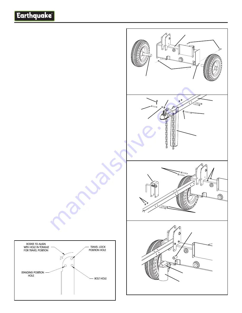
4. Attach the wheels to each side of the reservoir
(4300) by sliding the end of the spindle into the tubes
at the bottom of the reservoir. Make sure that the
holes line up as you insert the spindle. Secure in
place with two 5/16-18 x 2-1/4” bolts (48300) and
two 5/16-18 bi-way locknuts (60G56). Place one
bearing cover over the end of the hub and tap with
rubber mallet until it is seated against the hub.
DO
NOT STRIKE TOO HARD OR YOU WILL DAMAGE
THE COVER.
Repeat for the other wheel.
See
Figure 1.
NOTE: The rest of the assembly is easier done with
at least two people.
5. Next, attach kickstand (4306) to tongue (4304) using
one 3/8-16 x 3” bolt (4359), two 3/8” flat washers
(WF38), one 3/8-16 bi-way locknut (2104), one
3/8” x 2.75” pin (4334) and one hair clip (Hair-5).
Attach the kickstand to the tongue so that it will
support the weight of the log splitter as you
assemble the rest of the pieces.
DO NOT
OVERTIGHTEN - MUST SWING FREELY. See
Figure 2a & 2c.
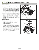
6. Next, attach the tongue to the reservoir using two
3/8-16 x 3” bolts (4359) and two 3/8-16 bi-way
locknuts (2104). Attach travel lock assembly to the
tongue using two 3/8-16 x 3” bolts (4359) and two
3/8-16 bi-way locknuts (2104). Position of pin should
be toward operator’s side.
See Figure 2b.
7. Next, remove the 3/4” x 2” pipe nipple (4357) from
the parts bag and insert it into the upper hole in the
reservoir. Now, remove the screw-on filter (4106)
from the parts bag and remove the replaceable filter
(4106A) from the cap. Thread the cap onto the
nipple at outlet end and tighten until the bottom of
the cap faces downward. Thread the filter onto the
cap after applying a thin film of oil to the rubber seal
to ensure that it does not tear.
See Figure 3.
For
W2808 proceed to step 10.
LOG SPLITTER ASSEMBLY INSTRUCTIONS
Figure 1
Figure 2a
Figure 3
Figure 2b
spindle
60G56
tube
48300
4300
HAIR-5
4334
2104
4359
WF38
WF38
4306
4304
4359
2104
4357
4106
4106A
NOTE
POSITION
of travel
lock
assembly
4359
2104
Figure 2c


