Page 9
LOG SPLITTER ASSEMBLY INSTRUCTIONS
NOTE: At least two people are required to lift and
assemble the beam to the reservoir.
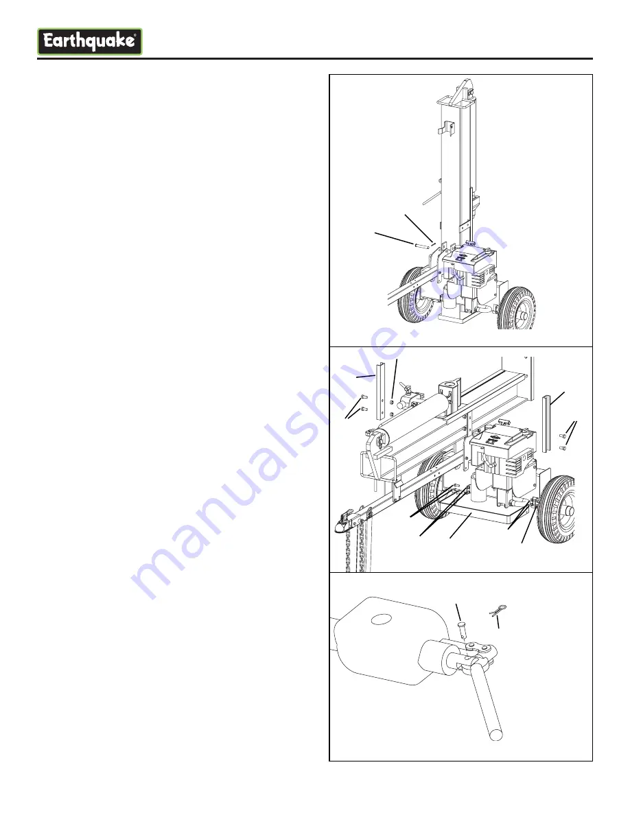
12. Remove the beam and stand it upright on the foot
as it would be in use. Roll the reservoir into position
and rotate the reservoir with the tongue until the
holes line up to insert the 5/8” x 4” pivot pin (4337).
Insert a cotter pin (4155) into hole in pin and bend
with pliers to secure.
See Figure 6.
13. Rotate the beam until it is horizontal. Install the
stripper bars (4314) facing upward using four
1/2-13 x 1” bolts (4363) and four 1/2-13 bi-way
locknuts (4117). Install the brush guard (4326)
using four 3/8-16 x 1” bolts (2102) and four 3/8-16
bi-way locknuts (2104).
See Figure 7.
14. Remove the high pressure hoses from the parts
box. Install a 60” hose (4210) from the top of the
valve (4100) to the filter (4106). Route the hose
over the top of the tongue and under the beam.
Next, remove the inlet hose (4210 for W2265;
60” long) or (4209 for W2808; 48” long) and install
between the pump outlet and the bottom of the
valve also routing over the tongue and under the
beam.
15. Move control valve handle to operation position.
Remove 1/4” pin (4190) and 1/16” cotter pin (4189)
from parts bag and insert pin through hole in control
valve handle and secure with cotter pin.
See
Figure 8.
16. Fill the reservoir with hydraulic oil but do not
overflow. Fill the engine with oil and gas as
required. Start the engine and operate the log
splitter running the wedge to the end of the beam
and back until it operates smoothly. Also, check for
leaks under pressure. Tighten as needed. Check
level of fluid in reservoir. Ensure that oil level is on
the dipstick; if not, add oil as needed. If the log
splitter will not operate smoothly, contact your
dealer.
Figure 6
4190
4189
Figure 8
4337
4155
4314
4363
4314
4363
4117
Figure 7
4326
2102
2102 (2)
2104
2104


