background image

Assembly


and


Operation


Instructions


90399_M52162_Oct_2021.docx


PAGE


3


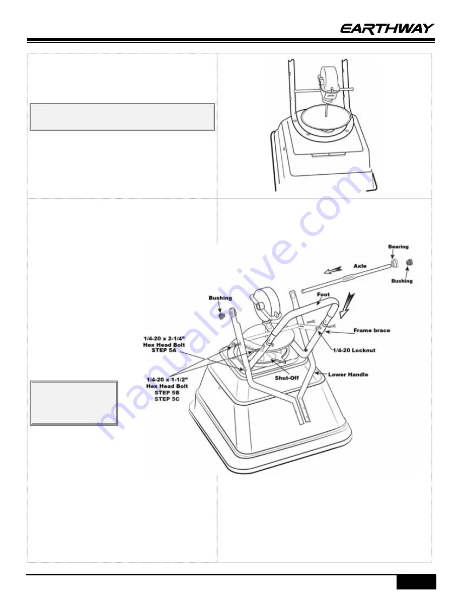
Step 4: 

Install


GEARBOX


by


inserting


the


PINION


SHAFT


into


hole


in


center


of


HOPPER


bottom.


The


word


“FRONT”


on


the


GEARBOX


must


point


to


Front


of


the


HOPPER.


NOTE:

 Place PolarTech brand towards the front of 

the hopper. 


Step 5: 

(A)


Install


LOWER


HANDLES


onto


FRAME


to


both


sides


as


shown.


Insert


″ 

bolt


through


hole


in


LOWER


HANDLE


and


through


hole


in


FRAME


install


locknut.


DO


NOT


TIGHTEN.


(B)


Now


insert


″ 

bolt


into


the


hole


in


LOWER


HANDLE,


then


through


FRAME


brace.


Next


into


threaded


connector


in


CROSS


BRACE.


DO


NOT


TIGHTEN


NOTE

: Numbers on 

frame brace must be 
facing toward gear 
box as shown. 

(C)


Install


the


FOOT


into


the


FRAME


and


align


the


bolt


holes


in


the


FOOT


and


the


FRAME


(a


Phillips


screwdriver


or


large


nail


is


helpful


to


align


the


parts)


(D)


Next


insert


″ 

bolt


through


other


end


of


FRAME


BRACE


and


through


hole


in


FRAME


through


the


FOOT


and


install


locknut.


Summary of Contents for Polar Tech 90399

Page 1: ...support team is standing ready to ensure your success Please contact us at www EarthWay com to see our full line of commercial lawn garden tools NOTE The large opening is designed to allow ice melt t...

Page 2: ...attern Do not use powdered materials as it will damage the gearbox Gears are permanently lubricated at the factory Do not open the GEARBOX or dirt may enter SPREADER ASSEMBLY INSTRUCTIONS Step 1 Remov...

Page 3: ...lt through hole in LOWER HANDLE and through hole in FRAME install locknut DO NOT TIGHTEN B Now insert 1 bolt into the hole in LOWER HANDLE then through FRAME brace Next into threaded connector in CROS...

Page 4: ...r pin through wheel and through AXLE Bend with pliers to prevent pin from falling out Step 8 Install COAST WHEEL onto the AXLE fully then using outside cotter pin hole insert 1 cotter pin through AXLE...

Page 5: ...Assembly and Operation Instructions 90399_M52162_Oct_2021 docx PAGE 5 TALL OPERATOR CONFIGUATION with the four handle holes use the bottom two holes for the guage and use the top hole for the spacer...

Page 6: ...A Thread hex nut onto the end of the pivot rod B Insert threaded end of the pivot rod into the shut off plate C Thread an additional hex nut on the end of the pivot rod Use a 7 16 wrench to secure the...

Page 7: ...ginal workmanship and materials for a period of one year to the end user with the original purchase receipt If a manufacturing non conformance is found EarthWay Products Inc at its discretion will rep...

Page 8: ...ESCRIPTION SERIES PART DESCRIPTION 1 40003 SQUARE SCREEN 9 60333 GEABOX ASSEMBLY 2 99342 HOPPER SHUTOFF ASSEMBLY 10 12110 9 ROUND DISHED IMPELLER 3 38144 HARDWARE KIT SS 3 1 3 94 11 70138 13 PNEUMATIC...

Reviews: