background image


4.


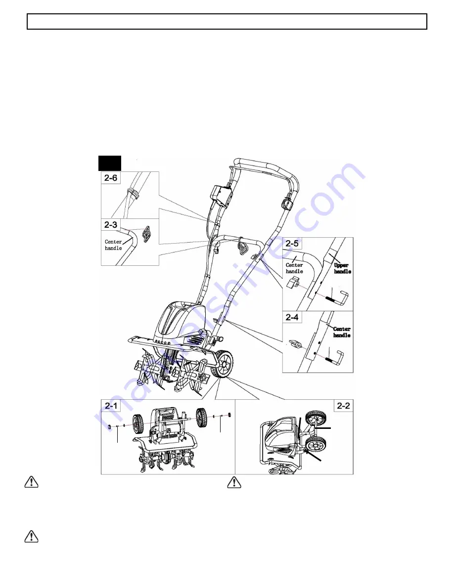
Slide the cord retainer onto the center handle        

section. (Fig. 2

-

3)


5.


Attach the center handle section to the lower handle 

sections using the two supplied M6 J

-

bolts and wing 

nuts. (Fig. 2

-

4)


6.


Fasten the upper handle section to the center handle 

section using the two supplied M6 J

-

bolts and wing 

nuts

.

(Fig. 2

-

5)


7.


Use the two supplied cable clips to secure the cord to 

the handle. (Fig. 2

-

6)


ASSEMBLY


5


Model TC70016


This product must be assembled correctly before use.


1.


Remove the screws (M5 X 12) and washers from 

each end of the wheel frame axle. Assemble the 

wheels onto the axle, then install washers and 

screws (M5 X 12) to secure. (Fig. 2

-

1)


2.


Press the hub caps into the wheels and cover the 

ends of the axles. You may use a hammer to seat 

them securely into the wheels. (Fig. 2

-

1)


3.


To lower wheel frame, push the lock button on back 

of motor housing to release the frame (Step A).     

Lower the wheel frame (Step B) and pull out the lock 

pin on lower handle section (Step C). Align lock pin  

to the hole in wheel frame then release it to lock the 

wheel frame in position. (Fig. 2

-

2)


WARNING: 

If any parts are damaged or missing do not 

operate this product until the parts are replaced.      

Failure to heed this warning could result in serious  

personal injury. Call our customer service help line at   

1

-

800

-

633

-

1501 for assistance.


WARNING: 

Do not connect to power supply until      

assembly is complete. Failure to comply could result in 

accidental starting and possible serious personal injury.


WARNING: 

Do not attempt to modify this product or 

create accessories not recommended for use with this 

product. Any such alteration or modification is misuse 

and could result in a hazardous condition leading to 

possible serious personal injury.


A


B


C


  2


M6


M6


M5x12


M5x12


Summary of Contents for TC70016

Page 1: ...CALL 1 800 633 1501 BETWEEN 8 AM 5 PM EST MONDAY FRIDAY FOR ASSISTANCE SAVE THIS MANUAL FOR FUTURE REFERENCE This product has been engineered and manufactured to our high standard for dependability ea...

Page 2: ...on the circuit or outlet to be used for the tiller cultivator Receptacles are available having built in GFCI protection and may be used It is possible to tie the extension cord and power cord in a kno...

Page 3: ...NG Do not operate the tiller cultivator near underground electrical cables telephone lines pipes or hoses If the tiller cultivator strikes a foreign body turn it off immediately wait for the tines to...

Page 4: ...lock pin RTC70016 10 3 Switch box and power cable assembly RTC70016 02 13 Motor housing RTC70016 24 4 Cable clip RTC70016 03 14 Protective shield RTC70016 33 5 Cord retainer RTC70016 04 15 Tine assem...

Page 5: ...ig 2 1 3 To lower wheel frame push the lock button on back of motor housing to release the frame Step A Lower the wheel frame Step B and pull out the lock pin on lower handle section Step C Align lock...

Page 6: ...e holes in Tine Hubs and shaft are aligned Insert Lock Pin into the through holes and pull Lock pin ring downward to lock the Pin into place Be sure to install Tines as shown in Fig 3 Tines cannot be...

Page 7: ...ny person or object directly in its path Hold the tiller cultivator firmly while starting The tines will pull the tiller cultivator forward during operation Lower the tines slowly into the ground bein...

Page 8: ...ooting Do not work on extremely steep slopes For preparing seed beds we recommend using one of these tilling patterns Tilling Pattern A Make two passes over area to be tilled the second at a right ang...

Page 9: ...the tine assemblies with new ones when necessary Call 1 800 633 1501 for assistance WARNING Injury can occur while working on the tines Wear protective gloves Tine Removal and Installation Fig 10 Lift...

Page 10: ...nutes before further use Abnormal noises Blade is jammed Lubrication running out Bolts nuts or other components are loose Switch off Wait till tines comes to a complete stop Remove jammed objects Till...

Page 11: ...at americanlawnmower com Be sure to provide all relevant information when you call or visit REPAIR PARTS Please record your serial number in the space provided below NAME OF ITEM Tiller Cultivator MOD...

Page 12: ...tly from an authorized retailer This warranty does not apply to any product new or used purchased through unauthorized third party channels ANY INCIDENTAL INDIRECT OR CONSEQUENTIAL LOSS DAMAGE OR EXPE...

Page 13: ...1501 ENTRE LAS 8 00 AM Y LAS 5 00 PM HORA DEL ESTE DE LOS ESTADOS UNIDOS GUARDE ESTE MANUAL PARA CONSULTAS FUTURAS Este producto fue dise ado y fabricado de acuerdo con nuestros altos est ndares de co...

Page 14: ...el amperaje de la etiqueta Ante la duda utilice el siguiente calibre m s grueso Cuanto m s bajo es el n mero de calibre m s grueso es el cable El cable de extensi n y el cable de alimentaci n se pued...

Page 15: ...tengan y verifique si hay da os Si fuera necesario repare las piezas da adas antes de volver a poner en marcha la herramienta Si el rotocultivador comienza a vibrar de manera inusual ap guelo de inmed...

Page 16: ...a rueda RTC70016 60 2 Gatillo RTC70016 17 12 Pasador de bloqueo RTC70016 10 3 Conjunto de cable de alimentaci n e interruptor RTC70016 02 13 Caja del motor RTC70016 24 4 Sujetador de cable RTC70016 03...

Page 17: ...del motor para soltar el bastidor Paso A Baje el bastidor de las ruedas Paso B y tire del pasador de bloqueo que se encuentra en el mango inferior Paso C Alinee el pasador de bloqueo con el orificio d...

Page 18: ...las p as como se muestra en la Fig 3 Las p as no pueden sujetarse si se ensamblan en otra secuencia de posici n de las p as Fig 3 En caso de que se pierdan o se extrav en los pasadores de bloqueo las...

Page 19: ...el rotocultivador si una persona u objeto se encuentra en su recorrido Sostenga el rotocultivador firmemente mientras lo enciende Las p as llevar n el rotocultivador hacia delante durante la operaci n...

Page 20: ...base de apoyo firme y segura No trabaje en pendientes demasiado pronunciadas Para preparar semilleros recomendamos usar estos patrones de labranza Patr n de labranza A Realice dos pasadas sobre el rea...

Page 21: ...eden producir lesiones mientras se trabaja con las p as Utilice guantes de protecci n Extracci n e instalaci n de p as Fig 10 Levante los aros de los pasadores de bloqueo y retire los pasadores de blo...

Page 22: ...rramienta Ruidos extra os La cuchilla est atascada Falta de lubricaci n Pernos tuercas u otros componentes flojos Apague la unidad Espere hasta que las p as se detengan por completo Quite los objetos...

Page 23: ...icanlawnmower com Aseg rese de proporcionar toda la informaci n relevante cuando nos llame o visite REPUESTOS Registre su n mero de serie en el espacio provisto a continuaci n NOMBRE DEL ELEMENTO Roto...

Page 24: ...por un distribuidor minorista autorizado Esta garant a no se aplica a cualquier producto nuevo o usado adquirido a trav s de canales de terceros no autorizados CUALQUIER P RDIDA ACCIDENTAL INDIRECTA...

Page 25: ...OM OU COMPOSEZ LE 1 800 633 1501 E 8 h 00 17 h 00 HEURE DE L EST POUR TOUTE ASSISTANCE CONSERVEZ CE MANUEL POUR POUVOIR LE CONSULTER ULT RIEUREMENT Ce produit a t con u et fabriqu selon notre norme le...

Page 26: ...la plaque signal tique En cas de doute utilisez le calibre imm diatement sup rieur Plus le num ro de calibre est bas plus le c ble est lourd Il est possible de nouer la rallonge et le c ble d alimenta...

Page 27: ...rrer Si le cultivateur la griffe commence vibrer de fa on anormale arr tez le imm diatement et recherchez la cause du probl me Des vibrations signalent g n ralement un probl me DANGER RISQUE DE COUPUR...

Page 28: ...7 12 Tige de verrouillage RTC70016 10 3 Ensemble contacteur et c ble d alimentation RTC70016 02 13 Carter du moteur RTC70016 24 4 Attache de c ble RTC70016 03 14 T le de protection RTC70016 33 5 Dispo...

Page 29: ...ge l arri re du carter de moteur pour d gager le ch ssis tape A Abaissez le ch ssis de roue tape B et retirez la goupille de verrouillage de la section inf rieure du guidon tape C Alignez la goupille...

Page 30: ...ge de verrouillage vers le bas pour bloquer la tige en place Assurez vous d installer les peignes comme illustr la Fig 3 Les peignes ne peuvent tre fix s si assembl s dans une autre s quence de positi...

Page 31: ...ersonne ou un objet se trouve directement sur le chemin de l appareil Maintenez fermement le cultivateur la griffe au d marrage Les dents font avancer le cultivateur la griffe pendant son fonctionneme...

Page 32: ...ir une position ferme et s re Ne travaillez pas sur des pentes trop abruptes Pour la pr paration des lits de semences nous recommandons d utiliser un de ces motifs de labourage Motif de labourage A Fa...

Page 33: ...Appelez le 1 800 633 1501 pour obtenir de l aide AVERTISSEMENT Un travail sur les dents entra ne des risques de blessures Portez des gants protecteurs Retrait et installation du peigne Fig 10 Levez le...

Page 34: ...ts anormaux La lame est coinc e Lubrification insuffisante Les boulons les crous ou d autres composants sont desserr s Arr tez le moteur Attendez que les dents s arr tent compl tement de tourner Enlev...

Page 35: ...com Veillez fournir toute l information pertinente lorsque vous nous appelez ou nous rendez visite PI CES DE RECHANGE Veuillez inscrire votre num ro de s rie dans l espace fourni ci dessous NOM DE L A...

Page 36: ...autoris Cette garantie ne s applique pas tout produit neuf ou usag achet par le biais de canaux tiers non autoris s TOUT DOMMAGE PERTE OU FRAIS CONS CUTIF INDIRECT OU CONS QUENT QUI POURRAIT R SULTER...

Reviews: