background image

5

elements of the RimMount™. First, loosen the thumbscrew so there is more 
than  enough  space  for  the  Delrin®  cushioned  rim-guide  to  clear  the  bottom 
of the drum rim. Then determine where on the drum rim you want to put the 
microphone, then put the “hook portion” of the RimMount bracket in that place 
on the drum rim. 

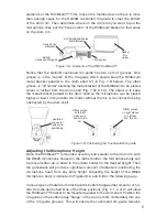
Soft Polyolefin® Coated

Metal Bracket

Rubber 

Mic

Holder

Delrin®

Cushioned Rim-guide

Hook Portion

of Bracket

Thumbscrew

Figure 7-A.  Elements of the RM1 RimMount™

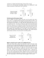
Notice  that  the  Delrin®  cushioned  rim-guide  has  two  sets  of  grooves.  One 
groove  is  in  the  “center”  of  the  rim-guide  which  should  keep  the  RImMount 
metal  bracket  parallel  to  the  drum  shell  (#1  in  Fig.  7-B  below).  The  other 
groove  is “off center” allowing the metal bracket of the RimMount to be placed 
closer or further from the drum shell (Fig. 7 #2 & #3). The object is to keep 
the metal bracket parallel to the drum shell so the microphone can be placed 
higher or lower in the rubber mic holder without the mic or its connector being 
obstructed by the drum shell.

Centered

Groove for 

typical mic 

positioning

Offset groove

on the left 

places mic 

closer to the 

rim

Offset groove

on right places 

mic further 

from the rim

1

2

3

Figure 7-B  Positioning the Cushioned Rim-guide

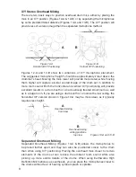
Adjusting the Microphone Height

Once the RimMount™ is mounted securely and parallel to the drum rim, with 
the DM20 microphone housed in the rubber holder, the microphone body can 
be moved either up or down in the rubber holder for the desired height. Then 
the gooseneck will provide a significant amount of latitude in positioning the 
microphone  head  from  any  body  height.  Adjusting  the  height  of  the  DM20 
microphone body is indicated in Figures 8-A and 8-B on the following page.

Various types of metal drum rims have the bottom flange either closer to or fur-
ther from the drum shell. One of the three positions (Fig. 7, 1, 2 or 3) will allow 
the RimMount™ bracket to be mounted parallel to the drum shell. Position the 
rim-guide so the bottom edge “flange” of the drum rim fits comfortably into one 
of the rim-guide grooves. This will ensure the cushioned rim-guide remains

Summary of Contents for DrumKit DK7

Page 1: ...User s Guide DK7 DrumKit An Entire New World of Pristine Drum Sound...

Page 2: ...www earthworksaudio com register All Earthworks products carry a limited warranty parts and labor To register your product you will need the serial number and series letter for each microphone You can...

Page 3: ...mKit Drum Microphone System 2 SR25 Cardioid Microphones overheads 4 DM20 DrumMic toms snare 1 SR20LS kickdrum 4 RM1 RimMount for DM20s 3 SRW3 Foam Windscreens for SR25s SR20LS 4 PW1 Windscreens for DM...

Page 4: ...nput overload protection Fig 1 B Such pads typically provide 10dB or 20dB of attenuation If your preamps have no pad prior to the preamp input an external XLR type microphone pad can be used such as t...

Page 5: ...ear Perfect Polar Response One of Earthwork s proprietary technologies is near perfect polar response i e very uniform frequency response over the front 160 degrees of the micro phone Conventional mic...

Page 6: ...on Inserting the DM20 Tom and Snare Microphone into the RM1 RimMount The RM1 RimMount is designed to allow the DM20 to be mounted on the side of a tom or snare in addition to miking either the top and...

Page 7: ...lder without the mic or its connector being obstructed by the drum shell Centered Groove for typical mic positioning Offset groove on the left places mic closer to the rim Offset groove on right place...

Page 8: ...le This will prevent the mi crophone diaphragm being forced against its backplate which could cause an unwanted pop or thump in the live sound or recording system Figures 9 A 9 B Positioning the Micro...

Page 9: ...B Miking the Head of a Tom A B Close Miking Toms with the DM20 The extended low frequency response of the DM20 DrumMic will provide a rich and full tom sound You can mike either the top and or bottom...

Page 10: ...ooth or an acoustically treated small room as well as in a large room If you are using a drum booth or a room with a low ceiling the horizontal X Y version shown in Figure 12 A may be more ideal as it...

Page 11: ...hone is placed close to where the two cymbals come together the bursts of air generated when the two cymbals close may result in an undesirable thumping or popping sound from the microphone Fig 14 C M...

Page 12: ...hich could cause the microphone to pop A For taller mic stands with angled boom B For short mic stands with boom parallel to floor Figures 17 A B Attach Mic Clip at XLR End of the Microphone EQ and Si...

Page 13: ...unt of EQ until you get the sound you want as all kickdrums are different It is also standard practice to sometimes use compression limiting and or gates expanders for kickdrum It is sug gested that y...

Page 14: ...12 NOTES...

Page 15: ...www earthworksaudio com register All Earthworks products carry a limited warranty parts and labor To register your product you will need the serial number and series letter for each microphone You ca...

Page 16: ...ween pins 2 3 Noise Weight 36lb 164g Frequency response Polar Pattern Cardioid Sensitivity 8mV Pa 42dBV Pa Power requirements 24 48V Phantom 10mA Peak acoustic input 150dB SPL 20Hz to 20kHz Signal to...

Reviews: