
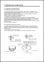

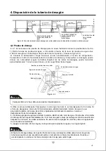
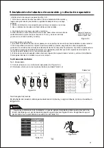


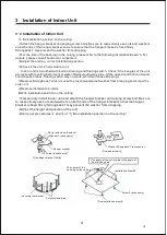
5.Instala
ción de
tuberías de conexión y
válvula de expansión
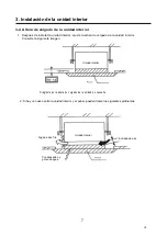
b.Dobl
ar
el tubo de conexión de pared fina (Fig. 5.3).
1.
Cort
e
una muesca del tamaño requerido en
la zona doblada del tubo aislado
, y
luego expon
ga
la tubería (
envuélvala
con aglutinante después de que se haya
doblado).
2.
Dobl
e
el radio tanto como sea posible para evitar
que se aplaste o se rompa
.
3.
Use
un
doblador de tuberías para hacer
dobleces más cerradas
.
Separe la tubería por
secciones para
que el
extremo
quede
recto
Figur
a
5.3
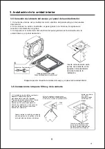
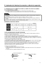
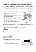
5-4 Conexión del tubo
5-4-1
Abocardado
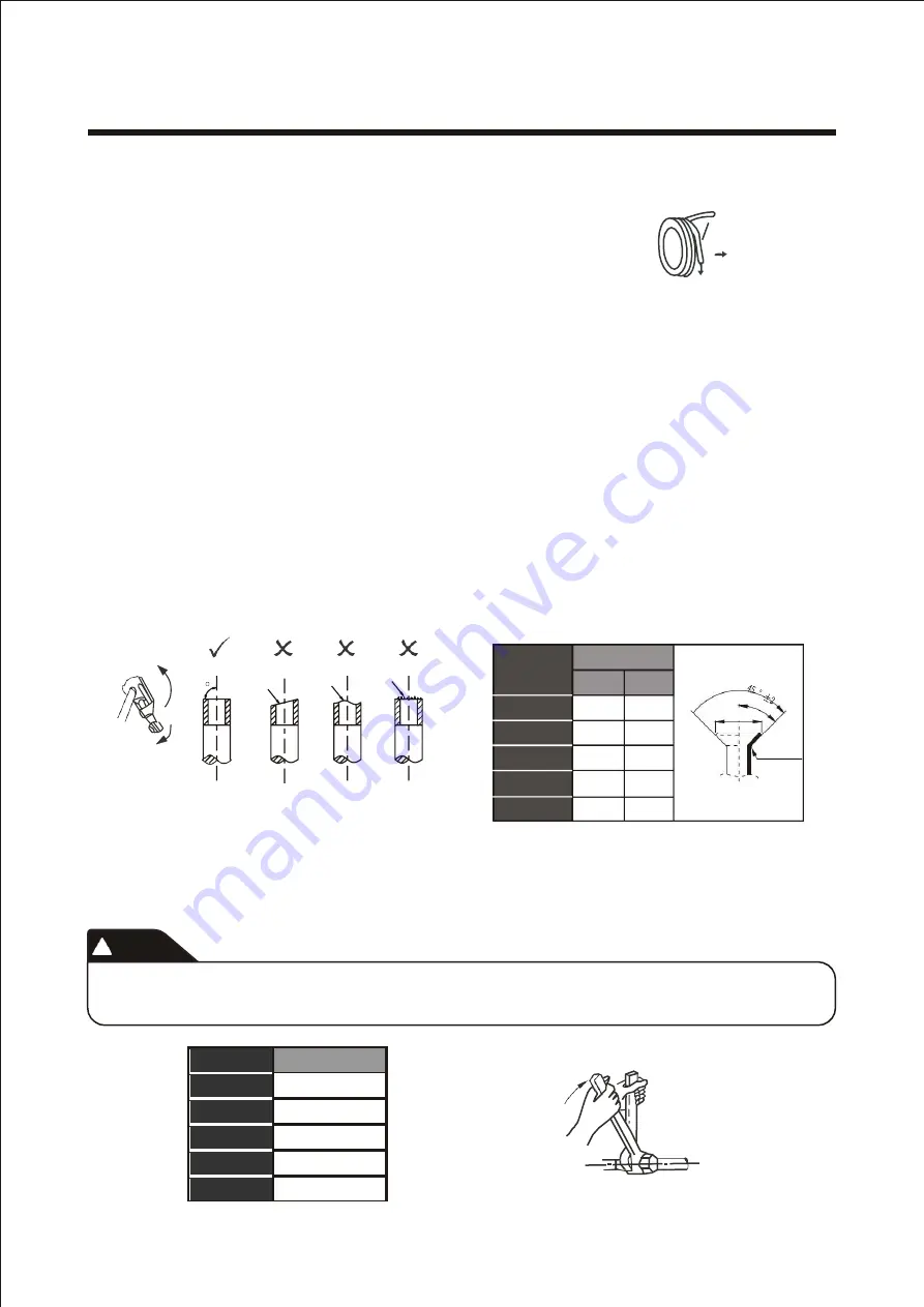
1)
Cort
e
la tubería con un
instrumento apropiado
(Ver Figura 5.4).
2)
Introduzca el tubo en la tuerca
abocardada
conectada (Tabla 5.2)
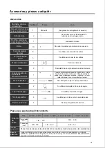
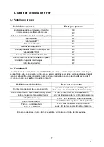
90
Inclinación
Irregularidad
Rebaba
Diámetro
externo (mm)
Tabl
a
5.2
90 °
± 4
A
Figur
a
5.4
R0.4
~
0.8
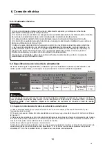
5-4-2
Asegurar las tuercas
En la tubería
de conexión
,
enros
que
las tuercas con la mano y luego con llaves
,
como se muestra en
la figura 5.5.
!
Atención
Según
las condiciones de la instalación, un par
de
apriete
demasiado grande
puede provocar una
rotura,
mientras que un par demasiado pequeño
puede provocar
fugas de aire.
A
segúrese de que el
par de torsión se ha atornillado de acuerdo con la Tabla 5.3.
Tabl
a
: 5.3
Figur
a
5.5
14
Par de
apriete
(
N.m
)
1/4
10
~
12
3/8
15
~
18
1/2
20
~
23
5/8
28
~
32
3/4
35 ~
40
1/4
A
(
mm
)
Max
.
Min
.
8.7
8.3
3/8
12.4
12.0
1/2
15.8
15.4
5/8
19.0
18.6
3/4
23.3
22.9
c. Usar tubería de cobre
según
mercado
y normativa
:
Si utiliza
tubería de cobre comprada en el mercado, debe utilizar el mismo tipo de
material aislante (el grosor suele ser superior a 10 mm, y
debe ser
aún más
grueso
si es un
a
zona húmeda
y
cerrada).
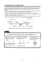
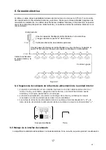
5-3-2 Disposición de la tubería
1)
Es necesario doblar la tubería o hacer
pasamuros.
La superficie de la sección de tubería doblada no
debe
exceder
1/3 de la superficie de la sección original. Al perforar
paredes o paneles
, asegúrese de colocar
casquillos de
protección. No se
deben hacer
líneas de soldadura dentro de los casquillos de protección. Al perforar la
pared exterior
de la tubería, asegúrese de sellarla firmemente con aglutinante para evitar
que entren impurezas
en
la tubería. La
tubería debe
estar
aislada
con
un tubo aislante adecuado
.
2)
El tubo de conexión encapsulado debe atravesar el agujero de la pared desde el exterior y entrar en la habitación.
Disponga l
as tuberías
con cuidado
de que no se rompan.
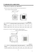
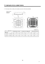
tamaño
de tuberías
(mm)
V.2


