background image

64

12

51
51
52
53

64

64

11

Final checks
Test run operation (manually)

11.1
11.2

77

77

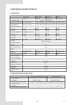
14.1
14.2

65

65

13

67
69

General guidelines
General symptoms
Operation parameter
Error codes

13.1
13.2
13.3
13.4

Initial start-up at low outdoor ambient temperature
Pre-operation checks
The circulation pump
Field settings

10.3
10.4
10.5
10.6

General
Electrical specifications

TEST RUN AND FINAL CHECKS

MAINTENANCE AND SERVICE

TROUBLE SHOOTING

14

TECHNICAL SPECIFICATIONS

78

15

INFORMATION SERVICING

V.1

Summary of Contents for ETH080VMA

Page 1: ...HERMAL 2 MONOBLOCK V 1 MANUAL DE INSTRUCCIONES INSTRUCTION MANUAL Escanee para ver este manual en otros idiomas y actualizaciones Scan for manual in other languages and further updates Manuel dans d a...

Page 2: ...as Cableado 9 1 9 2 9 3 9 4 9 5 9 6 9 7 APLICACIONES T PICAS RESUMEN DE LA UNIDAD PUESTA EN MARCHA Y CONFIGURACI N 35 CONTENIDO 1 2 3 4 5 2 1 Accesorios proporcionados con la unidad Selecci n de ubica...

Page 3: ...ncionamiento C digos de error 13 1 13 2 13 3 13 4 Puesta en marcha inicial en baja temperatura Comprobaciones Bomba de circulaci n Ajustes instalaci n 10 3 10 4 10 5 10 6 General Especificaciones el c...

Page 4: ...12 14 16 kW 8 10 12 14 16 kW 4 6 kW Retire la chapa hueca despu s de la instalaci n 4 6 kW Diagrama interno 12 16kW trif sica por ejemplo Sistema control el ctrico Bornero Sistema hidr ulico Sistema r...

Page 5: ...on muy importantes as que aseg rese de seguirlas atentamente Significado de los s mbolos de PELIGRO ADVERTENCIA ATENCI N y NOTA Indica una situaci n de peligro inminente que de no evitarse puede resul...

Page 6: ...pecificados y compruebe que todos los borneros est n protegidos del agua y otras fuerzas externas adversas Una conexi n o fijaci n incompleta puede dar lugar a incendios Cuando conecte la fuente de al...

Page 7: ...n ni o sin supervisi n debe realizar la limpieza y mantenimiento de usuario del aparato Mantenga a los ni os supervisados si est n cerca del aparato para asegurar que no juegan con la unidad Si el ca...

Page 8: ...ep sitos de agua caliente sanitaria Se pueden combinar con unidades fan coil suelo radiante radiadores de alta eficiencia de baja temperatura dep sitos de agua caliente sanitaria y kits solares que se...

Page 9: ...enumera a continuaci n Rango de funcionamiento por bomba de calor con posible limitaci n y protecci n Manual de instrucciones este libro Cantidad Manual funcionamiento Manual datos t cnicos Filtro en...

Page 10: ...es muy pesada evite inclinarla durante el transporte para que no se caiga ATENCI N Volumen de carga de refrigerante en la unidad de f brica Refrigerante kg Toneladas de equivalente CO2 4kW 1 40 0 95 6...

Page 11: ...a un lugar de instalaci n aprobado por el usuario donde se cumplan las siguientes condiciones Debe estar bien ventilado La unidad no debe molestar a los vecinos Debe soportar el peso y vibraci n de la...

Page 12: ...dad en lugares expuestos con frecuencia a la nieve aseg rese de elevar la base tanto como sea posible Si instala la unidad en un soporte a ada una placa resistente al agua de unos 100mm en la parte in...

Page 13: ...ci n para que la unidad no cause ruidos ni vibraci n durante el funcionamiento Siguiendo la ilustraci n explicativa asegure la unidad con pernos de fijaci n Prepare cuatro conjuntos de pernos de expan...

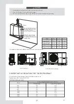
Page 14: ...mm A 200mm A mm 1000 1500 Unidad 4 6kW 8 16kW 7 4 Requisitos de dimensiones de instalaci n 7 4 1 En caso de instalaci n apilada 1 Si existen obst culos frente a la salida de aire 2 Si existen obst cul...

Page 15: ...iones en m ltiples filas para el tejado etc En caso de instalar varias unidades conectadas lateralmente por fila 500mm 500mm 1 2 H B2 A B1 C H Unidad A mm B1 mm B2 mm C mm 4 6kW 8 16kW 2500 1500 1000...

Page 16: ...rio opcional Tbt2 Sonda de temperatura inferior del tanque de equilibrio opcional P_o Bomba de circulaci n Zona A P_s Bomba solar Tsolar Sonda de temperatura solar Opcional Panel solar P_d Bomba tuber...

Page 17: ...l contacto seco de MIM2 se cierra Esta funci n no es v lida en modo de agua caliente dom stica Control del TBH CRT calentador r pido del tanque Se configura en la interfaz de usuario Ver 10 2 Resumen...

Page 18: ...MOSTATO DE PARED EL control por zonas del espacio en refrigeraci n o calefacci n se deben configurar en la interfaz de usuario Se puede configurar de tres formas CONFIGURACI N DE MODO ZONA NICA DOBLE...

Page 19: ...e configura a trav s del termostato de pared y la temperatura del agua se configura en la interfaz de usuario 1 Si se cierra cualquier CL en todos los termostatos el sistema se configura en modo refri...

Page 20: ...o calefacci n el encendido y apagado de la zona 2 la controlan los termostatos de sala de la zona 2 Cuando cualquier CL de todos los termostatos de la zona 2 se cierre la zona 2 se enciende Cuando tod...

Page 21: ...de agua sanitaria accesorio Vaso de expansi n suministro sobre el terreno T1 sensor de temperatura del flujo de agua total opcional C digo Unidad de montaje Dep sito de agua caliente sanitaria sumini...

Page 22: ...modo calefacci n cuando la temperatura de entrada de agua o la de ambiente sea muy baja y la temperatura de consigna de salida del agua es demasiado alta la AHS se encender autom ticamente 2 Cuando s...

Page 23: ...tes en la placa principal de la unidad maestra Consulte 9 3 1 y 9 7 6 3 El sistema tiene una funci n de autodireccionamiento Tras la puesta en marcha inicial la unidad maestra asignar direcciones a la...

Page 24: ...agua externa de la congelaci n Equilibra la presi n del sistema de agua Cuatro sensores de temperatura determinan la temperatura del agua y del refrigerante en varios puntos del circuito de agua 5 1 T...

Page 25: ...el producto real 8 10kW Placa control m dulo inverter PCB A Placa control del sistema de bomba de calor PCB B 4 6kW Placa principal del m dulo hidr ulico Placa control m dulo inverter PCB A Placa cont...

Page 26: ...de la PCB B s lo para unidades trif sicas 12 14 16kW Trif sica Placa principal del m dulo hidr ulico Placa control del sistema de bomba de calor PCB B Placa control del sistema de bomba de calor PCB...

Page 27: ...Puerto para sonda temp tanque de equilibrio 12 Terminal sonda temperatura inferior tanque de equilibrio 13 Terminal sonda temp tanque ACS 14 Terminal sonda temp zona 2 agua de salida Terminal sonda te...

Page 28: ...N32 Terminal entrada L para puente rectificador CN501 Terminal entrada N para puente rectificador CN502 1 2 3 CN20 CN19 CN32 CN502 CN23 CN6 CN501 4 8 5 6 7 9 10 1 2 3 4 5 Unidad Unidad C digo C digo 6...

Page 29: ...exterior y sonda temp condensador CN9 Terminal para interruptor alta presi n CN13 Terminal sonda temp descarga CN8 Terminal sonda presi n CN4 Terminal para comunicaci n con placa del hidrobox CN29 Re...

Page 30: ...a m dulo IPM CN1 Terminal entrada P_out para m dulo IPM CN5 1 2 3 4 5 6 7 Unidad de montaje Unidad de montaje C digo C digo 9 10 11 12 13 8 Terminal W de conexi n del compresor CN19 Terminal U de cone...

Page 31: ...ctrica 2 CN7 Terminal para v lvula de 4 v as CN18 Reservado CN11 Terminal para sonda temperatura ambiente y sonda temp condensador CN9 8 10 11 12 13 Terminal para cinta calefacci n el ctrica1 CN10 Te...

Page 32: ...i n L3 CN200 Alimentaci n L2 CN201 Alimentaci n L1 L1 Alimentaci n N CN203 Reservado CN211 Alimentaci n para la placa de control CN30 Filtro de energ a L1 L1 Filtro de energ a L2 L2 Filtro de energ a...

Page 33: ...Contactor calefactor auxiliar KM1 Contactor calefactor auxiliar KM2 C digo Unidad C digo Unidad 1 2 3 4 5 Contactor calefactor auxiliar KM3 1 2 4 3 5 Monof sica 8 16kW con calefactor auxiliar Monof si...

Page 34: ...la fuente de alimentaci n o en la bomba drene el sistema como se muestra en la figura siguiente NOTA Si no se elimina el agua del sistema en climas muy fr os mientras no se usa la unidad el agua cong...

Page 35: ...ura siguiente 2 El volumen del vaso de expansi n debe ajustarse al volumen total del sistema de agua 3 Dimensionar la expansi n del circuito de calefacci n y refrigeraci n 9 4 2 Volumen de agua y dime...

Page 36: ...e 3 v as en el circuito de agua use una v lvula de tipo bola para garantizar la separaci n total entre el circuito de agua caliente sanitaria y el circuito de agua de calefacci n por suelo radiante Cu...

Page 37: ...de agua a la v lvula de llenado y abra la v lvula Aseg rese de que la v lvula de purga de aire autom tica est abierta al menos 2 vueltas Consulte la Figura 3 3 3 Llene de agua hasta que el man metro i...

Page 38: ...debido a las ondas de alta frecuencia Nunca instale un compensador ya que puede dar lugar a accidentes 9 7 2 Resumen del cableado La ilustraci n inferior ofrece un esquema de las conexiones el ctrica...

Page 39: ...de usuario Cable del termostato de sala Cable de control de la bomba solar Cable de control de la bomba de circulaci n exterior Cable de control de la bomba de ACS SV2 cable de control de la v lvula d...

Page 40: ...ulte la imagen 9 7 6 para obtener la posici n de los puertos en la unidad La cinta de calefacci n el ctrica de la v lvula de expansi n la cinta de calefacci n el ctrica del intercambiador de calor de...

Page 41: ...para que encaje correctamente 9 7 4 Requisito de dispositivo de seguridad Use el destornillador adecuado para apretar los tornillos del bornero Los destornilladores peque os pueden da ar la cabeza de...

Page 42: ...LA A Unidad exterior Corriente Compresor OFM 27 31 13 50 0 10 0 50 264 38 220 240 50 198 14 50 0 17 1 50 29 32 264 38 220 240 50 198 30 32 15 50 0 17 1 50 264 198 38 220 240 50 25 38 0 10 0 50 220 240...

Page 43: ...interruptor de alta velocidad de 30 mA 0 1 s Utilice cable de 3 hilos apantallado El calentador auxiliar predeterminado es la opci n 3 para el calentador auxiliar de 9kW Si se necesita un calentador a...

Page 44: ...ra Esclava 1 H1 H2 Esclava 2 H1 H2 Esclava X H1 H2 Resistencia adicional SW9 ON OFF SW9 L1 L2 L3 N Fusible L1 L2 L3 N Fusible L1 L2 L3 N Fusible L1 L2 L3 N ATENCI N 1 La funci n paralela del sistema s...

Page 45: ...diferentes al mismo terminal de suministro de energ a puede provocar el sobrecalentamiento de los cables debido a un cableado suelto Ver Figura 9 2 Cuando conecte al terminal de la fuente de alimentac...

Page 46: ...omba circulaci n ext bomba zona 1 Bomba zona 2 CN11 SV2 V lvula de 3 v as 11 Bomba tuber a ACS 23 N SV1 V lvula de 3 v as Bomba energ a solar 20 3OFF 1 SL1 2 SL2 3 H 4 C 5 6 1ON 7 1OFF 8 9 10 11 12 24...

Page 47: ...V1 5 6 16 5 6 16 CN11 25 26 1 2 3 4 5 6 7 8 9 10 CN30 CN7 27 28 29 30 31 32 4 Para apagado remoto 30 29 32 25 26 27 28 31 7 12 11 10 9 18 8 7 5 23 22 24 1 2 13 3 4 6 20 14 15 17 19 16 21 6 8 9 10 5 4...

Page 48: ...cable del termostato como se describe en la imagen de arriba y dependen de la aplicaci n M todo A RT puede controlar la calefacci n y la refrigeraci n individualmente como el controlador para FCU de...

Page 49: ...trol de doble zona M todo C El m dulo hidr ulico est conectado con dos termostatos de ambiente mientras que la interfaz de usuario FOR SERVICEMAN configura el TERMOSTATO DE HABITACI N en DOBLE ZONA C...

Page 50: ...a 2 se apaga C 3 Cuando HT COM y CL COM se detectan como 0VDC la unidad se apaga C 4 cuando HT COM y CL COM se detectan como 12VDC se encienden tanto la zona 1 como la zona 2 NOTA 9 Salida de se al de...

Page 51: ...nte est encendida la unidad funciona normalmente 3 Cuando la se al EVU est apagada la se al SG est apagada el modo ACS est apagado y el TBH no es v lido la funci n de desinfecci n no es v lida El tiem...

Page 52: ...ie su valor si T1SETH1 T1SETH2 intercambie su valor T4 20 19 18 17 16 15 14 13 12 11 10 9 8 7 6 5 4 3 2 1 0 1 T1S 38 38 38 38 38 37 37 37 37 37 37 36 36 36 36 36 36 35 35 35 35 2 T1S 37 37 37 37 37 36...

Page 53: ...os switches DIP 10 2 1 Ajuste de funci n Los interruptores DIP S1 S2 y S4 est n ubicados en la placa del m dulo hidr ulico de control principal consulte 9 3 1 Placa de control principal del m dulo hid...

Page 54: ...leado Disyuntor del calentador de refuerzo No olvide encender el disyuntor del calentador de refuerzo solo se aplica a las unidades con tanque de agua caliente sanitaria opcional instalado Cableado de...

Page 55: ...m xima Tasa de caudal m 3 h Resistencia al agua KPa 2 87 29 1 2 71 34 2 2 49 42 0 2 16 53 8 1 89 63 4 1 53 77 4 1 16 83 8 0 91 84 8 0 73 85 0 0 59 85 0 0 50 84 9 0 41 84 7 12 16kW La bomba mantiene la...

Page 56: ...os de error 10 6 Configuraci n de instalaci n La unidad debe configurarse para adaptarse al entorno de instalaci n clima exterior opciones instaladas etc y la demanda del usuario Hay varios ajustes de...

Page 57: ...RVICEMAN 10 6 1 Ajuste modo ACS ACS DHW Agua caliente sanitaria Vaya a MENU FOR SERVICEMAN 1 DHW MODE SETTING Pulse OK para acceder a las siguientes p ginas 1 DHW MODE SETTING YES YES YES YES NON ADJU...

Page 58: ...se OK para acceder a la siguiente p gina Si s lo configura WATER FLOW TEMP en YES o s lo ROOM TEMP en YES se muestran las siguientes p ginas Si configura WATER FLOW TEMP y ROOM TEMP en YES mientras qu...

Page 59: ...s con el clima 10 6 6 Termostato de pared El ROOM THERMOSTAT Termostato de pared se usa para configurar si el termostato de pared est disponible MENU FOR SERVICEMAN 6 ROOM THERMOSTAT Pulse OK para acc...

Page 60: ...TEST RUN Active the settings and active the TEST RUN OK CONFIRM NO YES Please wait 5 10 RESTORE FACTORY SETTINGS Si selecciona POINT CHECK se muestran las siguientes p ginas Pulse para desplazarse a...

Page 61: ...guiente p gina Durante la ejecuci n de la prueba del MODO CALOR la temperatura objetivo predeterminada del agua de salida es 35 C El IBH calentador auxiliar interno se encender despu s de que el compr...

Page 62: ...abierta Si se selecciona PRECALENTAMIENTO DEL SUELO despu s de presionar OK se mostrar la siguiente p gina 12 1 PREHEATING FOR FLOOR 30 C 72 HOURS ADJUST T1S t_fristFH ENTER EXIT Use para mover el cu...

Page 63: ...cado del piso se describe en la siguiente imagen t_DRYUP t_HIGHPEAK T1S t t_DRYD T_DRYPEAK Seleccionado OPERATE FLOOR DRYING con el cursor use para desplazarse a YES y pulse OK Se muestra la siguiente...

Page 64: ...0 600 5 MIN 1 18 t_DHWHP_MAX Tiempo m ximo de funcionamiento continuo de la bomba de calor en modo PRIORIDAD ACS 90 10 600 5 MIN 1 20 PUMP RUNNING TIME Tiempo que la bomba de ACS seguir funcionando 5...

Page 65: ...peratura ambiente de funcionamiento m xima para calentar en modo autom tico 17 10 17 1 5 1 WATER FLOW TEMP Habilita o deshabilita la TEMP FLUJO AGUA 0 NO 1 S 1 0 1 1 5 2 ROOM TEMP Habilita o deshabili...

Page 66: ...OTO ON OFF 1 TBH ON OFF 2 AHS ON OFF 0 0 2 1 15 2 SMART GRID Activa o desactiva SMART GRID Red inteligente 0 NO 1 S 0 0 1 1 15 3 T1b Tw 2 Activa o desactiva el T1b Tw 2 0 NO 1 S 0 0 1 1 15 4 Tbt1 Acti...

Page 67: ...ajo de 1 bar llene el sistema con agua Filtro de agua Limpiar el filtro de agua V lvula de alivio de presi n de agua Verifique el funcionamiento correcto de la v lvula de alivio de presi n girando la...

Page 68: ...l compresor no arranca calefacci n de habitaciones o calefacci n de agua sanitaria POSIBLES CAUSAS ACCI N CORRECTIVA Es posible que la unidad funcione fuera de su rango de funcionamiento la temperatur...

Page 69: ...e agua y luego comun quese con su distribuidor local CAUSAS POSIBLES ACCI N CORRECTIVA El funcionamiento del calentador auxiliar no est activado Se utiliza demasiada capacidad de la bomba de calor par...

Page 70: ...no se alcanza el punto de ajuste la calefacci n requiere calor pero la unidad permanece en modo ACS CAUSAS POSIBLES ACCI N CORRECTIVA La superficie de la bobina en el tanque no es lo suficientemente g...

Page 71: ...o de la bomba El voltaje de funcionamiento es diferente y la desviaci n es diferente El valor de visualizaci n es 0 cuando el voltaje es inferior a 198 V NOTA OPERATION PARAMETER 01 IDU TARGET FREQUEN...

Page 72: ...ia del sensor 2 El conector del sensor T5 est aflojado Vuelva a conectarlo 3 El conector del sensor T5 est mojado o hay agua Retire el agua y seque el conector Agregar adhesivo impermeable 4 El sensor...

Page 73: ...nector y agregue adhesivo impermeable 3 El sensor TW_out falla sustit yalo Fallo del sensor de temperatura del agua de salida Tw_out 1 Verifique la resistencia del sensor 2 El sensor de Ta est en la i...

Page 74: ...m dulo hidr ulico paralelo Fallo del sensor de temperatura del agua de salida final T1 La PCB de RT Ta est configurada para ser v lida en la interfaz de usuario pero la placa de transferencia del term...

Page 75: ...or y apl quele un adhesivo a prueba de agua 3 La sonda Th est averiada sustit yala Error en sonda de temperatura de aspiraci n Th 1 El cable que conecta la placa de control PCB B y la placa de control...

Page 76: ...llo de sensor de presi n Consulte P0 Protecci n por baja presi n en modo refrigeraci n Pe 0 6 ha ocurrido 3 veces en 1 hora Consulte H6 H6 se muestra 10 veces en 2 horas 1 Hay un error en los par metr...

Page 77: ...a y p rguelo 2 La presi n de agua es inferior a 0 1Mpa cargue agua hasta que la presi n est en un rango de 0 15 0 2Mpa 3 Hay una sobrecarga de volumen de refrigerante Aj stelo al volumen correcto 4 La...

Page 78: ...atura demasiado alta del m dulo transductor 1 Voltaje de alimentaci n de la unidad demasiado bajo aumente el voltaje hasta el rango requerido 2 El espacio entre las unidades es demasiado estrecho para...

Page 79: ...n velocidad nula Error excepci n de verificaci n del equipo 1 Compruebe la presi n del sistema de la bomba de calor 2 Compruebe la resistencia de fase del compresor 3 Compruebe continuidad de las l ne...

Page 80: ...anguera Enfriada por agua 3 2L 3 bar 12 65 C 5 25 C 25 35 C 5 43 C 25 43 C Monof sica 12 14 16 kW 865 1385 526mm 129kg 155kg G5 4 BSP Enfriada por agua 2 0L Monof sica 4 6 8 10 12 14 16kW Trif sica 12...

Page 81: ...dar lugar a incendio o explosi n Cualquier posible fuente de llama incluidos los cigarrillos se debe mantener lo suficientemente lejos del lugar de instalaci n reparaci n desinstalaci n y eliminaci n...

Page 82: ...l equipo en uso Los componentes de por s seguros son los nicos que se pueden manipular en un entorno con presencia de gas inflamable El tester debe mostrar valores correctos Sustituya los componentes...

Page 83: ...el refrigerante del sistema sea para mantenimiento o para desinstalaci n se recomienda que se recupere todo el refrigerante Al transferir el refrigerante a los cilindros compruebe que s lo se usan cil...

Page 84: ...efactor auxiliar opcional Sonda temperatura entrada refrigerante l quido Sonda temperatura entrada refrigerante gas Sonda temperatura salida agua Sonda temperatura entrada agua V lvula de purgado de a...

Page 85: ...en la salida de drenaje el usuario Conecte la cinta de revestimiento de alambre en la salida de drenaje a la junta de alambre XT3 XT3 A la cinta calefactora de la salida de drenaje 4 6kW XT3 A la cin...

Page 86: ...otencia de la cinta calefactora electr nica no debe exceder los 40 W 200 mA voltaje de suministro 230 V CA XT3 A la cinta calefactora de la salida de drenaje 12 14 16kW Monof sica XT3 A la cinta calef...

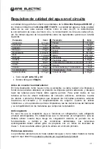
Page 87: ...idad exterior En toda instalaci n tanto nueva como ya existente se debe realizar una limpieza a fondo de las tuber as utilizando un producto de limpieza qu mico adecuado y despu s lavar las tuber as p...

Page 88: ...cualquier naturaleza 8 P rdidas o da os en el software o soportes de informaci n 9 Aver as producidas por factores externos como alteraciones de corriente sobrecargas el ctricas suministro de voltaje...

Page 89: ...icipales habituales tienen que ser recogidos selectivamente para optimizar la recuperaci n y reciclado de los componentes y materiales que los constituyan y reducir el impacto en la salud humana y el...

Page 90: ...k volume requirement 8 1 8 2 8 3 8 4 Disassembling the unit Main components Electronic control box Water piping Filling water Water piping insulation Field wiring 9 1 9 2 9 3 9 4 9 5 9 6 9 7 Dimension...

Page 91: ...s Operation parameter Error codes 13 1 13 2 13 3 13 4 Initial start up at low outdoor ambient temperature Pre operation checks The circulation pump Field settings 10 3 10 4 10 5 10 6 General Electrica...

Page 92: ...14 8 10 12 14 16 kW 4 6 kW 8 10 12 14 16 kW 4 6 kW Please remove the hollow plate after installation Internal layout 12 16kW 3 phase for example Electric Control System Terminal Block Hydraulic Syste...

Page 93: ...into the following types They are quite important so be sure to follow them carefully Meanings of DANGER WARNING CAUTION and NOTE symbols Indicates an imminently hazardous situation which if not avoid...

Page 94: ...d fire Make sure all wiring is secure Use the specified wires and ensure that terminal connections or wires are protected from water and other adverse external forces Incomplete connection or affixing...

Page 95: ...Children should not play with the unit Cleaning and user maintenance should not be done by children without supervision Children should be supervised to ensure that they do not play with the applianc...

Page 96: ...They can be combined with fan coil units floor heating applications low temperature high efficiency radiators domestic hot water tanks and solar kits which are all field supplied A wired controller i...

Page 97: ...s with slings The slings can be fitted into foreseen sleeves at the base frame that are made specifically for this purpose 4 BEFORE INSTALLATION In heating mode the water flowing temperature TW_out ra...

Page 98: ...Prevent the unit from falling due to improper inclination during handling CAUTION 5 IMPORTANT INFORMATION FOR THE REFRIGERANT This product has the fluorinated gas which is forbidden to release to air...

Page 99: ...d one that meets with your customer s approval Places that are well ventilated Places where the unit does not disturb neighbors Safe places which can bear the unit s weight and vibration and where the...

Page 100: ...irect sunlight so that it is not influenced by the sun s heat otherwise protection may be possible to the unit In case of strong wind and the wind direction can be foreseen refer to the figures below...

Page 101: ...the unit may not cause any vibrations or noise during its operation In accordance with the foundation drawing in the figure fix the unit securely by means of foundation bolts Prepare four sets each of...

Page 102: ...rain hole is covered by rubber plug If the small drain hole can not meet the drainage requirements the big drain hole can be used at the same time Drain hole V 1 7 4 Servicing space requirements 7 4 1...

Page 103: ...n case of multiple row installation for roof top use etc In case of installing multiple units in lateral connection per row 500mm 500mm B2 A B1 C Unit A mm B1 mm B2 mm C mm 4 6kW 8 16kW 2500 1500 1000...

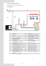
Page 104: ...lance tank upper temperature sensor Optional 14 Shut off valve Field supply 4 4 Tbt2 Balance tank lower temperature sensor Optional 15 Filling valve Field supply 5 P_o Outside circulation pump Field s...

Page 105: ...is invalid in DHW mode TBH tank booster heater control The TBH function is set on the user interface See 10 2 DIP switch settings overview 1 When the TBH is set to be valid TBH can be turned on via T...

Page 106: ...4 1 Automatic air purge valve 21 Thermostat transfer board Optional 4 2 Drainage valve RT 1 7 Low voltage room thermostat Field supply 5 P_o Outside circulation pump Field supply RT8 High voltage roo...

Page 107: ...ly Cooling or heating mode is set via the room thermostat water temperature is set on the user interface 1 When any CL of all the thermostats close system will be set at cooling mode 2 When any HL of...

Page 108: ...Field supply RT8 High voltage room thermostat Field supply 23 2 SV3 Mixing valve Field supply Tw2 Zone 2 water flow temperature sensor Optional 12 P_c zone 2 circulation pump Field supply FHL 1 n Floo...

Page 109: ...NOTE 18 2 Drainage valve must beinstalled at the lowest position of the piping system V 1 8 3 Cascade system Automatic air purge valve...

Page 110: ...19 V 1 n d e d n d Automatic air purge valve r d r manometer d r...

Page 111: ...water tank power supply if applicable before removing doors 1 and 2 Parts inside the unit may be hot Door 1 To access to the compressor and electrical parts Door 1 Door 2 To access to the hydraulic c...

Page 112: ...freezing Balances water system pressure Four temperature sensors determine the water and refrigerant temperature at various points in the water circuit 5 1 T2B 5 2 T2 5 3 T1 optional 5 4 TW_out 5 5 TW...

Page 113: ...er to the actual product 8 10kW Main control board of hydraulic module Inverter module control board PCB A Main control board of heat pump sysem PCB B Inverter module control board PCB A Main control...

Page 114: ...lic module Filter board PCB C at back of the PCB B only for 3 phase unit 12 14 16kW 3 phase Main control board of hydraulic module Inverter module control board PCB A Main control board of heat pump s...

Page 115: ...12 Port for balanced water tank of dowm temp sensor 13 Port for domestic hot water tank temp sensor 14 Port for outlet water for zone 2 temp sensor Port for solar panel temp sensor Port for variable...

Page 116: ...CB B CN32 Input port L for rectifier bridge CN501 Input port N for rectifier bridge CN502 1 2 3 CN20 CN19 CN32 CN502 CN23 CN6 CN501 4 8 5 6 7 9 10 1 2 3 4 5 Assembly unit Assembly unit Coding Coding 6...

Page 117: ...ansion value CN33 27 28 29 Digital display DSP1 Port for chassis electrical heating tape CN16 optional Port for compressor eletric heating tape 1 CN7 Port for 4 way value CN6 Port for SV6 value CN5 Po...

Page 118: ...ly unit Assembly unit Coding Coding 9 10 11 12 13 8 Compressor connection port W CN19 Compressor connection port U CN17 Power Input port L3 CN15 Power Input port L1 CN16 Power Input port L2 CN7 Port f...

Page 119: ...for ground wire CN38 Port for eletric heating tape2 CN7 Port for 4 way value CN18 Reserved CN11 Port for outdoor ambient temp sensor and condenser temp sensor CN9 8 10 11 12 13 Port for eletric heati...

Page 120: ...r ltering L1 L1 Power ltering L2 L2 Power ltering L3 L3 PCB C 3 phase 12 14 16kW PE1 PE2 PE3 CN202 CN201 CN200 CN203 CN204 CN205 CN206 CN212 CN211 CN8 CN213 CN214 CN30 2 5 4 3 6 13 12 7 8 9 10 11 14 1...

Page 121: ...protector Backup heater contactor KM1 Backup heater contactor KM2 Coding Assembly unit Coding Assembly unit 1 2 3 4 5 Backup heater contactor KM3 1 2 4 3 5 1 phase 8 16kW with backup heater 1 phase 3...

Page 122: ...e figure below NOTE If water is not removed from the system in freezing weather when unit is not used the frozen water may damage the water circle parts NOTE 31 The unit is equipped with a water inlet...

Page 123: ...ansion vessel of 8L that has a default pre pressure of 1 5 bar To assure proper operation of the unit the pre pressure of the expansion vessel might need to be adjusted 1 Check that the total water vo...

Page 124: ...3 way valve in the water circuit Preferably choose a ball type 3 way valve to guarantee full separation between the domestic hot water and floor heating water circuit When using a 3 way valve or a 2 w...

Page 125: ...C Directives Connect the water supply to the fill valve and open the valve Make sure the automatic air purge valve is open at least 2 turns Fill with water pressure of approximately 2 0 bar Remove air...

Page 126: ...f the capacitor due to high frequency waves Never install a phase advancing capacitor as it could lead to an accident The illustration below gives an overview of the required field wiring between seve...

Page 127: ...C 3 200mA a AC 2 200mA a 6 7 8 Outside circulation pump control cable Solar pump control cable AC 2 200mA a AC 2 200mA a 1 2 5 7 8 6 4 H 25 T D A K K K K J G E L L 9 B CN11 CN7 CN30 1 A 2 B 3 X 4 Y 5...

Page 128: ...rovide only the switch signal Please refer to image of 9 7 6 to get the ports position in the unit Expansion valve E Heating tape Plate heat exchanger E Heating tape and Flow switch E Heating tape sha...

Page 129: ...rewdriver to tighten the terminal screws Small screwdrivers can damage the screw head and prevent appropriate tightening Over tightening the terminal screws can damage the screws Attach a ground fault...

Page 130: ...TOCA A MFA A MSC A RLA A KW FLA A Outdoor Unit Power Current Compressor OFM 1 1 1 1 27 31 13 50 0 10 0 50 264 38 220 240 50 198 14 50 0 17 1 50 29 32 264 38 220 240 50 198 30 32 15 50 0 17 1 50 264 1...

Page 131: ...8kW 10kW 12kW 14kW 16kW 12kW 3 PH 14kW 3 PH 16kW 3 PH Maximum overcurrent protector MOP A 31 31 32 32 43 43 43 27 27 27 Wiring size mm2 6 0 6 0 8 0 8 0 10 0 10 0 10 0 4 0 4 0 4 0 1 phase 4 16kW and 3...

Page 132: ...nnection diagram 3N Master unit Slave unit 1 H1 H1 Slave unit 2 1 H1 H Slave unit x 1 H1 H Build out resistor Only the last IDU requires adding the build out resistor at H1 and H2 L1 L2 L3 N Fuse L1 L...

Page 133: ...cular wiring terminal with the insulation casing see Figure 9 1 If circular wiring terminal with the insulation casing cannot be used please make sure that Do not connect two power cords with differen...

Page 134: ...one1 pump Pumpc zone2 pump CN11 SV2 3 way valve SV1 3 way valve 11 DHW pipe pump 23 N SV1 3 way valve SV1 3 way valve Solar energy pump 20 3OFF 1 SL1 2 SL2 3 H 4 C 5 6 1ON 7 1OFF 8 9 10 11 12 24 23 N...

Page 135: ...27 28 29 30 31 32 2 For 3 way valve SV1 SV2 and SV3 SV1 5 6 16 5 6 16 CN11 25 26 1 2 3 4 5 6 7 8 9 10 CN30 CN7 27 28 29 30 31 32 4 For remote shut down 30 29 32 25 26 27 28 31 7 12 11 10 9 18 8 7 5 23...

Page 136: ...1 25 26 1 2 3 4 5 6 7 8 9 10 CN7 CN30 27 28 29 30 31 32 15 3 CN11 25 26 1 2 3 4 5 6 7 8 9 10 CN7 CN30 27 28 29 30 31 32 15 3 4 L1 L1 HEAT H COOL C HEAT H L1 There are two optional connect method depen...

Page 137: ...tat while user interface FOR SERVICEMAN set ROOM THERMOSTAT to DOUBLE ZONE C 1 When unit detect voltage is 230VAC between H and L1 zone1 turns on When unit detect voltage is 0VAC between H and L1 zone...

Page 138: ...ure Fix the cable with cable ties to the cable tie mountings to ensure stress relief C 2 When unit detect voltage is 12VDC between CL and COM zone2 turn on according to climate temp curve When unit de...

Page 139: ...5 6 7 8 9 10 CN7 CN30 27 28 29 30 31 32 10 22 Control port signal type Voltage Maximum running current A Wiring size mm2 Type 1 220 240VAC 0 2 0 75 1 when EVU signal is on the unit operate as below DH...

Page 140: ...0 19 18 17 16 15 14 13 12 11 10 9 8 7 6 5 4 3 2 1 0 1 T1S 38 38 38 38 38 37 37 37 37 37 37 36 36 36 36 36 36 35 35 35 35 2 T1S 37 37 37 37 37 36 36 36 36 36 36 35 35 35 35 35 35 34 34 34 34 3 T1S 36 3...

Page 141: ...be set as following State In the setting the wired controller if T4C2 T4C1 then exchange their value if T1SETC1 T1SETC2 then exchange their value 1 2 3 4 1 2 3 4 S1 S2 ON OFF 1 2 3 4 S4 T4 10 T4 15 15...

Page 142: ...t the fuses or the locally installed protection devices are of the size and type specified in 14 Technical specifications Make sure that no fuses or protection devices have been bypassed Backup heater...

Page 143: ...um output Flow rate m 3 h Water resistance KPa 2 87 29 1 2 71 34 2 2 49 42 0 2 16 53 8 1 89 63 4 1 53 77 4 1 16 83 8 0 91 84 8 0 73 85 0 0 59 85 0 0 50 84 9 0 41 84 7 12 16kW Pump maintains maximum ou...

Page 144: ...imate installed options etc and user demand A number of field settings are available These settings are accessible and programmable through FOR SERVICEMAN in user interface 10 6 Field settings CAUTION...

Page 145: ...stic hot water Go to MENU FOR SERVICEMAN 1 DHW MODE SETTING Press OK The following pages will be displayed 10 6 1 DHW MODE SETTING 1 DHW MODE SETTING YES YES YES YES NON ADJUST 1 1 DHW MODE 1 2 DISINF...

Page 146: ...following page will be displayed If you only set WATER FLOW TEMP to YES or only set ROOM TEMP to YES The following pages will be displayed If you set WATER FLOW TEMP and ROOM TEMP to YES meanwhile set...

Page 147: ...AT ADJUST If you set DOUBLE ZONE and ROOM TEMP to YES meanwhile set WATER FLOW TEMP to YES or NON the following page will be displayed Homepage zone 1 2 Addition page zone 2 Double zone is effective I...

Page 148: ...ctive the settings and active the TEST RUN OK CONFIRM NO YES Please wait 5 10 RESTORE FACTORY SETTINGS If POINT CHECK is selected the following pages will be displayed Press to scroll to the component...

Page 149: ...following page will be displayed During HEAT MODE test running the default target outlet water temperature is 35 C The IBH internal backup heater will turn on after the compressor runs for 10 min Afte...

Page 150: ...TING FOR FLOOR is selected after press OK the following page will be displayed 12 1 PREHEATING FOR FLOOR 30 C 72 HOURS ADJUST T1S t_fristFH ENTER EXIT Use to scroll the cursor to YES and press OK the...

Page 151: ...ill be displayed Use to scroll the cursor to YES and press OK Floor drying will turn off The target outlet water temperature during floor drying up described in the picture below t_DRYUP t_HIGHPEAK T1...

Page 152: ...last 210 90 300 5 MIN 1 17 t_DHWHP_RESTRICT he operation time for the space heating cooling operation 30 10 600 5 MIN 1 18 t_DHWHP_MAX the maximum continuous working period of the heat pump in DHW PRI...

Page 153: ...LOW TEMP Enable or disable the WATER FLOW TEMP 0 NON 1 YES 1 0 1 1 5 2 ROOM TEMP Enable or disable the ROOM TEMP 0 NON 1 YES 0 0 1 1 5 3 DOUBLE ZONE Enable or disable the ROOM THERMOSTAT DOUBLE ZONE 0...

Page 154: ...OFF M1 M2 Define the function of the M1M2 sw itch 0 REMOTEON OFF 1 TBH ON OFF 2 AHS ON OFF 0 0 2 1 15 2 SMART GRID Enable or disable the SMART GRID 0 NON 1 YES 0 0 1 1 15 3 T1b Tw 2 Enable or disable...

Page 155: ...1 bar fill water to the system Water filter Clean the water filter Water pressure relief valve Check for correct operation of the pressure relief valve by turning the black knob on the valve counter...

Page 156: ...he unit is turned on but the compressor is not starting space heating or domestic water heating POSSIBLE CAUSES CORRECTIVE ACTION The unit maybe operate out of its operation range the water temperatur...

Page 157: ...water inlet and outlet shut off valves first and then contact your local dealer POSSIBLE CAUSES CORRECTIVE ACTION Backup heater operation is not activated Too much heat pump capacity is used for heat...

Page 158: ...in DHW mode POSSIBLE CAUSES CORRECTIVE ACTION Surface of coil in the tank not large enough The same solution for Symptom 7 TBH or AHS not available Heat pump will stay in DHW mode untill t_DHWHP_MAX...

Page 159: ...The operating voltage is different and the deviation is different The display value is 0 when the voltage is less than 198V NOTE OPERATION PARAMETER 01 IDU TARGET FREQUENCY 46Hz ADDRESS FREQUENCY LIM...

Page 160: ...or Final outlet water temp sensor T1 fault 1 Check the resistance of the sensor 2 The T5 sensor connector is loosen Reconnect it 3 The T5 sensor connector is wet or there is water in remove the water...

Page 161: ...water in remove the water make the connector dry add waterproof adhesive 3 The TW_out sensor failure change a new sensor Outlet water temp sensor Tw_out fault 1 Check the resistance of the sensor 2 Th...

Page 162: ...71 V 1...

Page 163: ...proof adhesive 3 The Th sensor failure change a new sensor Suction temperature sensor Th error 1 wire doesn t connect between main control board PCB B and main control board of indoor unit connect the...

Page 164: ...P0 Low pressure protection in cooling Pe 0 6 occurred 3 times in an hour Refer to H6 H6 displayed 10 times in 2 hours 1 The EEprom parameter is error rewrite the EEprom data 2 EEprom chip part is brok...

Page 165: ...correctly And install the winding in the right location DHW mode Water tank heat exchanger is smaller Cooling mode 1 Heat exchanger cover is not removed Remove it 2 Heat exchanger is dirty or somethin...

Page 166: ...cer module temperature too high protection 1 Power supply voltage of the unit is low increase the power voltage to the required range 2 The space between the units is too narrow for heat exchange Incr...

Page 167: ...n 1 Check the Heat pump system pressure 2 Check the phase resistance of compressor 3 Check the U V W power line connection sequence between the inventer board and the compressor 4 Check the L1 L2 L3 p...

Page 168: ...water inlet outlet Water drain volume Maximum working pressure MWP Type Pressure relief valve water circuit heating cooling heating cooling domestic hot water by heat pump 1 phase 4 6 kW 718 1295 429...

Page 169: ...all be displayed 7 Ventilated area Ensure that the area is in the open or that it it adequately ventilated before breaking into the system or conducting any hot work A degree of ventilation shall cont...

Page 170: ...lammable refrigerants but the sensitivity may not be adequate or may need re calibration Detection equipment shall be calibrated in a refrigerant free area Ensure that the detector is not a potential...

Page 171: ...rdance with the manufacturer s instructions Storage of packed unsold equipment Storage package protection should be constructed such that mechanical damage to the equipment inside the package will not...

Page 172: ...20 21 81 V 1...

Page 173: ...heating tape at the drainage outlet by client Connect the wireCeating tape at the drainage outlet to the wire joint XT3 XT3 To the heating tape of drainage outlet 4 6kW XT3 To the heating tape of drai...

Page 174: ...to the actual product The power of the E heating tape shall not exceed 40W 200mA supply volatge 230VAC NOTE XT3 To the heating tape of drainage outlet 12 14 16kW 1 phase XT3 To the heating tape of dra...

Page 175: ...5 Water hardness 50ppm Before connecting the outdoor unit In any installation both new and existing a thorough cleaning of the pipes should be carried out using a suitable chemical cleaning product a...

Page 176: ...es of any nature 8 Loss or damage to software or information media 9 Faults produced by external factors such as current disturbances electrical surges excessive or incorrect voltage supply radiation...

Page 177: ...mal unsorted municipal waste stream appliances must be collected separately in order to optimize the recovery and recycling of the materials they contain and reduce the impact on human health and the...

Page 178: ...nidad interior _________________________________________________ Modelo Unidad exterior ____________________________________________________ N serie Unidadexterior ____________________________________...

Page 179: ...ua stas no estar n cubiertas por la garant a as como las bombas intercambiadores etc 9 Fugas de agua visibles S NO 10 Limpieza de filtro y comprobaci n visual del estado del agua 11 Presi n de agua 12...

Page 180: ...e debe limitar la temperatura m xima a 65 C para evitar quemaduras al cliente 23 Cu ntos metros hay desde la m quina al dep sito de ACS se recomienda menos de 5m y un m ximo de 10m para un correcto fu...

Page 181: ...ruptores diferenciales CLASE B para evitar problemas de ruidos Pueden instalarse interruptores de CLASE A siempre y cuando sean superinmunizados No instale diferenciales de la clase AC ya que no est n...

Page 182: ...V 2...

Page 183: ...Escanee para ver este manual en otros idiomas y actualizaciones Scan for manual in other languages and further updates Manuel dans d autres langues et mis jour Manual em outras l nguas e actualiza es...

Reviews: