46
The unit shall be configured by the installer to match the installation environment (outdoor climate, installed options, etc.) and
user demand. A number of field settings are available. These settings are accessible and programmable through “FOR
SERVICEMAN” in user interface.
10.7 Field settings
When power on the unit, "1%~99%" is displayed on the user interface during initialization. During this process the user interface
cannot be operated.
Powering on the unit
Procedure
To change one or more field settings, proceed as follows.
Temperature values displayed on the wired controller (user interface) are in °C.
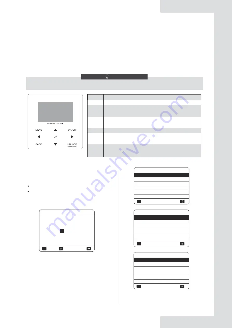
Keys
Function
MENU
• Go to the menu structure(on the home page)
BACK
• Come back to the up level
◄►
▼▲ • Navigate the cursor on the display
• Navigate in the menu structure
• Adjust settings
ON/OFF
• Turn on/off the space heating/cooling operation or DHW
mode
• Turn on/or off functions in the menu structure
UNLOCK
• Long press for unlock /lock the controller
• Unlock /lock some functions such as "DHW temperature
adjusting"
OK
• Go to the next step when programming a schedule in the
menu structure; and confirm a selection to enter in the
submenu of the menu structure.
NOTE
Press
▼
▲
to navigate and press
▼
▲
to adjust the
numerical value. Press OK. The password is 234, the
following pages will be displayed after putting the
password:
About FOR SERVICEMAN
"FOR SERVICEMAN" is designed for the installer to set
the parameters.
How to go to FOR SERVICEMAN
Go to MENU> FOR SERVICEMAN. Press OK:
Setting the composition of equipment.
Setting the parameters.
Please input the password:
ADJUST
OK
ENTER
0
0 0
FOR SERVICEMAN
OK
ENTER
FOR SERVICEMAN
1. DHW MODE SETTING
2. COOL MODE SETTING
3. HEAT MODE SETTING
4. AUTO MODE SETTING
5. TEMP.TYPE SETTING
6. ROOM THERMOSTAT
1/3
Press ▼ ▲ to scroll and use "OK" to enter submenu.
OK
ENTER
FOR SERVICEMAN
3/3
7. OTHER HEATING SOURCE
8. HOLIDAY AWAY MODE SET
TING
9. SERVICE CALL SETTING
10. RESTORE FACTORY SETTINGS
11. TEST RUN
12. SPECIAL FUNCTION
OK
ENTER
FOR SERVICEMAN
2/3
13. AUTO RESTART
14. POWER INPUT LIMITATION
15. INPUT DEFINE
16. CASCADE SET
17. HMI ADDRESS SET
V.2
Summary of Contents for ETH220VMA
Page 164: ...V 2...


